7.1 Introduction
The Real Time Clock (RTC) is a feature that can keep counting the time using external back-up battery when main system power-off. In this design a 32-bits counter is implemented for second counting. The conversion from second to time and date is calculated by software.
This design also provides an alarm feature that can be used to allow main system to 'wake up' after shut down to execute tasks in a certain moment. The alarm setting in seconds, the conversion from time and date to second is calculated by software.
Back-up power source can used a Super Cap or a coin battery (like CR2032), and build-in charging circuit without any external component.
The control registers locate at RGST Table Group116 registers which memory map address are 0x9C003A00~0x9C003A7F. The SP7021 RTC function include below features.
- Sustain more than one year with 250ma-H battery.RTC connect to the backup power pin, charge battery without adding any charging circuit. (Should be for hardware purpose, can be removed)
- RTC with alarm timer module has its own output pin. (Not shown in block diagram, or this feature is for hardware purpose)interrupt signal internally .
- Backup power failure flag (which hardware or software flag ?) to Group116.16 bit13~12 bat cmp hyt) to indicate the RTC information is not reliable when V-battery is lower than safe voltage. (Hardware or software usage ?)User can read this flag to monitor battery status.
7.2 Function Diagram
A generalized function diagram of RTC is shown in Figure 7-1.
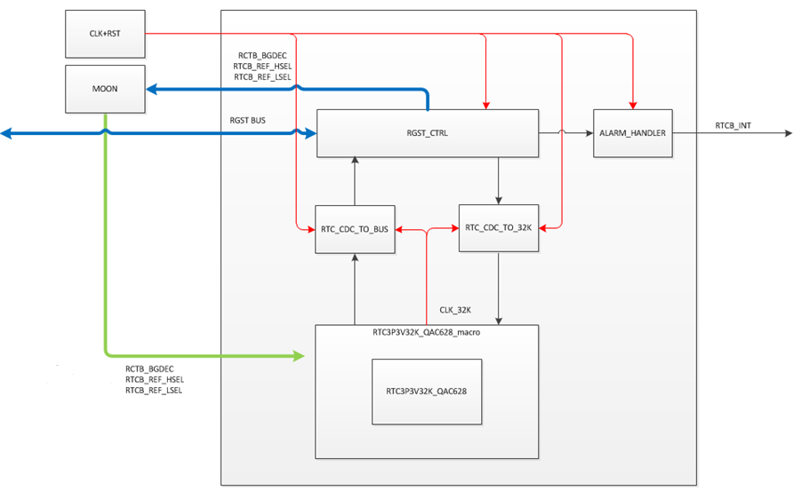
Figure 7-1 RTC Functional Blocks
RTC operates in two modes that are normal and back-up mode.
In the normal mode, when system power on, the power supply is come from VDD33. System can get current time from REG-bus and can set alarm time by REG-bus.
In the back-up mode, when system power off, the backup domain power supply by supper CAP or battery. The main system can be wake up when alarm alert.
| Anchor | ||||
|---|---|---|---|---|
|
...
Address | Group No. | Register Name | Description | |
|---|---|---|---|---|
0x9C003A00 | G116.0 | Reserved | Reserved | |
0x9C003A04 | G116.1 | Reserved | Reserved | |
0x9C003A08 | G116.2 | Reserved | Reserved | |
0x9C003A0C | G116.3 | Reserved | Reserved | |
0x9C003A10 | G116.4 | Reserved | Reserved | |
0x9C003A14 | G116.5 | Reserved | Reserved | |
0x9C003A18 | G116.6 | Reserved | Reserved | |
0x9C003A1C | G116.7 | Reserved | Reserved | |
0x9C003A20 | G116.8 | Reserved | Reserved | |
0x9C003A24 | G116.9 | Reserved | Reserved | |
0x9C003A28 | G116.10 | Reserved | Reserved | |
0x9C003A2C | G116.11 | Reserved | Reserved | |
0x9C003A30 | G116.12 | Reserved | Reserved | |
0x9C003A34 | G116.13 | Reserved | Reserved | |
0x9C003A38 | G116.14 | Reserved | Reserved | |
0x9C003A3C | G116.15 | Reserved | Reserved | |
0x9C003A40 | G116.16 | rtc ctrl | RTC Control | |
0x9C003A44 | G116.17 | rtc timer out | Get Timer | |
0x9C003A48 | G116.18 | rtc divider cnt out | Get Divider Cnt | |
0x9C003A4C | G116.19 | rtc timer set | Set Timer | |
0x9C003A50 | G116.20 | rtc alarm set | Set Alarm | |
0x9C003A54 | G116.21 | rtc user data | User Data Keep | |
0x9C003A58 | G116.22 | rtc reset record | Get Reset Records | |
0x9C003A5C | G116.23 | rtc batt charge ctrl | Battery Charge Control | |
0x9C003A60 | G116.24 | rtc trim ctrl | Trimming ControlReserved | Reserved |
0x9C003A64 | G116.25 | rtc otp ctrl | OTP ControlReserved | Reserved |
0x9C003A68 | G116.26 | Reserved | Reserved | |
0x9C003A6C | G116.27 | Reserved | Reserved | |
0x9C003A70 | G116.28 | Reserved | Reserved | |
0x9C003A74 | G116.29 | Reserved | Reserved | |
0x9C003A78 | G116.30 | Reserved | Reserved | |
0x9C003A7C | G116.31 | rtc ip version | IP Version |
...
116.22 Get Reset Records (rtc reset record)
Address: 0x9C003A58
Reset: 0x0000 0000
Briefly state the purpose of this record register
HW will update "reset_record" bits before reset , so user can check this item to know the reset reason.
| Field Name | Bit | Access | Description |
| Reserved | 31:16 | RO | |
| Reserved | 15:12 | RO | |
| reset_record | 11:0 | RW | Reset record bit0 : EXT RST B POR External Power on Reset bit1 : MO SYSTEM RST B System Software Reset bit2 : IOP SYS RST B bit3 : RI WATCHDOG SYS RST B bit4 : STC WATCHDOG SYS RST B bit5 : STC WATCHDOG2 SYS RST B bit6 : IOP WATCHDOG SYS RST B bit7 : LVD RSTB bit8 : POR RST B POR bit9˜11 : N/A |
...
| Field Name | Bit | Access | Description |
| Bit Write Mask | 31:16 | RW | |
| Reserved | 15:4 | RO | |
| bat_charge_rsel | 3:2 | RW | Choose charge resistor path 2'b00: 200 Ohm resistor path (default) |
| bat_charge_dsel | 1 | RW | Choose the path with / without diode 0: without diode (default) |
| bat_charge_en | 0 | RW | Battery charger 0: disable (default) 1: enable |
116.24 Trimming Control (rtc trim ctrl)Trim is for internal use only ? Reserved (Reserved)
Address: 0x9C003A60
Reset: 0x0000 0000
Field Name | Bit | Access | Description | Bit Write Mask | 31:16 | RO |
| ref_lsel | 15:12 | RW | 1.9V REF gen trimming select, every step is 2.87% (de-fault=4'b0000) 4'b0000=0% 4'b0010=2.87% 4'b0100=5.74% 4'b0110=8.61% 4'b1000=11.48% 4'b1010=-25.75% 4'b1100=-28.65% 4'b1110=-31.51% 4'b0001=-2.87% 4'b0011=-5.74% 4'b0101=-8.6% 4'b0111=-11.47% 4'b1001=-14.33% 4'b1011=-17.2% 4'b1101=-20.06% 4'b1111=-22.92% | |||
| ref_hsel | 11:8 | RW | 2.2V REF gen trimming select, every step is 2.5% (de- fault=4'b0000) 4'b0000=0% 4'b0010=2.5% 4'b0100=4.99% 4'b0110=7.48% 4'b1000=9.96% 4'b1010=12.45% 4'b1100=14.94% 4'b1110=17.43% 4'b0001=-2.49% 4'b0011=-5% 4'b0101=-7.51% 4'b0111=-10.01% 4'b1001=-12.51% 4'b1011=19.92% 4'b1101=22.41% 4'b1111=24.9% | |||
bgdec | 7:4 | RW | 1.2V Band-gap trimming select, every step is 3% (de- fault=4'b0000) | |||
test_sel | 3:1 | RW | Trim Test Select | |||
trim_en | 0 | RW | Enable register trimming control |
...
Reserved | 31:0 | RO |
116.25 Reserved (Reserved)
Address: 0x9C003A64
Reset: 0x0000 0000
Should be for internal use only
Field Name | Bit | Access | Description | Bit_Write_Mask||||||||
Reserved | 31: | 16RW | Reserved | 15:1 | RO | otp_load | 0 | RW | Load data of D-flip flop from OTP-level shift, which is used for voltage-trimming control 0: disable (default) 1: enable0 | RO |
116.26 Reserved (Reserved)
Address: 0x9C003A68
Reset: 0x0000 0000
...