1920.1 Introduction
The HDMI TX module is stand for "High Definition Multimedia Interface" to transmit high quality video and audio in a single cable. This HDMI TX IP is composed of video, audio and HDCP cipher engine and intends to be integrated to a SoC to deliver high quality video and audio over a single cable. SP7021 totally supports HDMI1.4 specification, the main features list as below.
About Video
...
The HDMI TX control registers locate at RGST Table Group 380~387 which memory map address are 0x9C00BE00~0x9C00C1FF.
...
20.2 Function Diagram
A generalized function diagram of HDMI is shown in Figure 1920-1.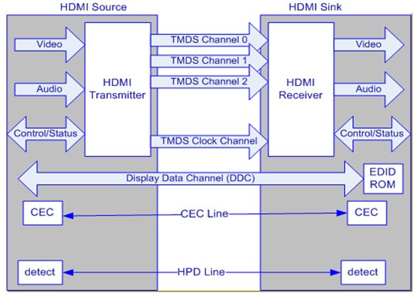
Figure 1920-1 Generic HDMI Functional Blocks
Each blocks description are as below:
...
A HDMI TX function diagram shows in Figure 1920-2.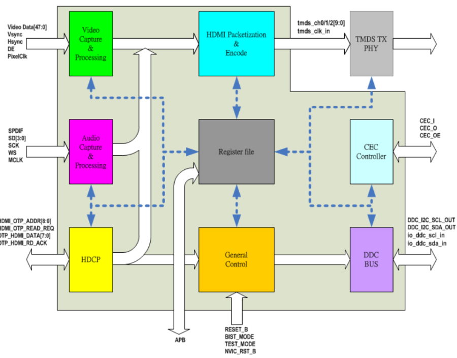
Figure 1920-2 HDMI TX Functional Blocks
There are 8 digital sub-blocks in the HDMI TX module of SP7021.
- Video Capture & Processing: Used to capture video data and process video conversion, such as color space conversion.
- Audio Capture & Processing: Used to capture audio data and process audio packetization.
- HDCP: Used to process HDCP authentication between source and sink.
- HDMI packetization: Used to generate TMDS timing protocol and transmit HDMI packets.
- General Control: This block will generate interrupts and resets; the clocks generator also resides here.
- DDC BUS: The hardware DDC (I2C) master to deal with the DDC channel transaction between source and sink.
- CEC: The hardware CEC processor can be a CEC channel transceiver.
- Register File: The register file is to be an interface between host and this module to control HDMI TX.
...
20.3 Video Path
This HDMI TX module incorporates various video processing modules to perform video conversion such as color space and range as required, and packs into 3 TMDS channels with 8-bits bus each. The detail blocks are drawn as figure 1920-3.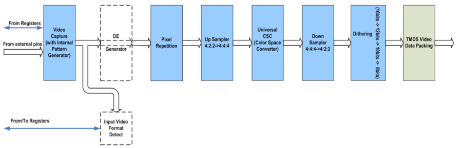
Figure 1920-3 Video Path
Three channel YCbCr 4:4:4 <-> two channel YCbCr4:2:2 converters dealing with at most 16-bits video data per channel and a universal color space converter are implemented. For universal CSC composed of one 3x3 matrix, standard ITU-R BT601 and ITU-R BT709 with F(full)/L(limit), F/F, L/F, L/L ranges conversion are supported, and coefficients are configurable according to parameters input as well.
This video processing also has dithering engine to convert 16bits/per channel to 12/10/8bits/per channel. The dithering process is a noise diffusion process for high-intensity-resolution images, which is used to reduce false contouring when the intensity-resolution is decreased.
The video capture receives video data from MPEG side. Because of specific application, this video capture only supports RGB/YCbCr444/YCbCr422 parallel bus input.
For debug purpose, there is an internal video pattern generator in video capture, which provides two patterns, one is gray levels for RGB; the other is color bar for YCbCr.
...
20.4 Audio Path
This IP supports 2 types of digital audio input channel. One is I2S, the other is SPDIF. I2S can convey L-PCM and HBR (compressed and bit rate > 6.144Mbps, like DTS-HD Master Audio, Dolby MAT), while SPDIF can convey L-PCM and compressed (IEC61937) digital audio.
Digital audio is captured by I2S or SPDIF , then passed them to AUDIO FIFO and packaged into Audio Sample Packet as described in HDMI specification.
Another auxiliary module is ACR module for "Audio Clock Regeneration". This module calculates the "Cycle Time Stamp (CTS)" according to input N value, and packages them into "ACR" packet
. 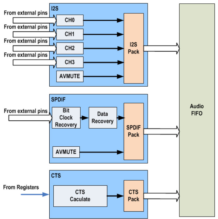
Figure 1920-4 Audio Path
...
20.5 HDCP
Figure 1920-5 shows the HDCP function block.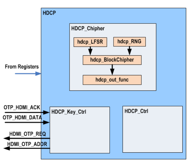
Figure 1920-5 HDCP Block
HDMI incorporates HDCP as content protection mechanism during transmitting copyright video and audio data. The SP7021 HDMI TX module embedded a HDCP engine to deal with this task.
The HDCP engine will generate security keys and uses them to encrypt the content. Before transmitting encrypted data, HDMI TX needs to do HDCP authentication with HDMI RX by exchanging HDCP public keys with each other. The detail process can be referred in HDCP specification 1.4.
The HDCP keys should be stored in non-violated memory in a safe place. The SP7021 HDMI TX module incorporates a predefined OTP interface protocol to access HDCP key. By this interface, HDMI TX can get the HDCP key from OTP then does HDCP encryption flow.
...
20.6 DDC Bus
The DDC bus exchange configuration and status between Source and Sink through I2C. The Sink's configuration and capabilities description is stored in the Extended Display Identification Data (EDID) ROM. The Source shall use I2C commands to read information from a Sink's EDID with a slave address.
...
20.7 Hot Plug Detect (HPD)
An HDMI Sink shall not assert high voltage level on its Hot Plug Detect pin when the EDID is not available for reading. The Hot Plug Detect pin may be asserted only when the +5V Power line from the Source is detected.
A Source may use a high voltage level Hot Plug Detect signal to initiate the reading of EDID data. A Source shall assume that any voltage within the range specified for High voltage level indicates that a Sink is connected and that EDID is readable.
An HDMI Sink shall indicate any change to the contents of the EDID by driving a low voltage level pulse at (least 100 msec) on the Hot Plug Detect pin.
...
20.8 Digital Visual Interface (DVI)
SP7021 can also support DVI 1.0 specification. The Group 380.8 SYSTEM CTRL1 register bit0 can select the supported mode. Set bit0=0 for DVI mode, set bit0=1 for HDMI mode.
...
20.9 System State Control
The firmware will control in the 4 states, they are INIT, HPD, RSEN and HDCP state. The operation flow is shown in figure 1920-6. Each state operation describe in table 1920-1.
Current State | Next State | Jump Condition |
INIT | INIT | Initialize HW and SW. |
HPD | Go to HPD state after initialization. | |
HPD | HPD | Set AVMUTE, detect HPD, read EDID and parse EDID. |
RSEN | Go to RSEN state when HPD detected and EDID detected or timeout. | |
RSEN | RSEN | Wait HDMI RX stable: enabled, A/V packet configured and TMDS ready. |
HPD | Go back to HPD state when HPD out is detected. | |
HDCP | Go to HDCP state when HDMI TX configuration is finished. | |
HDCP | HDCP | Check HDCP and clear AVMUTE to start to transfer. |
HPD | Go to HPD state when HDP out is detected. | |
RSEN | Go back to RSEN state when HDMI RX out or A/V setting changed. |
Table 1920-1 System State Description 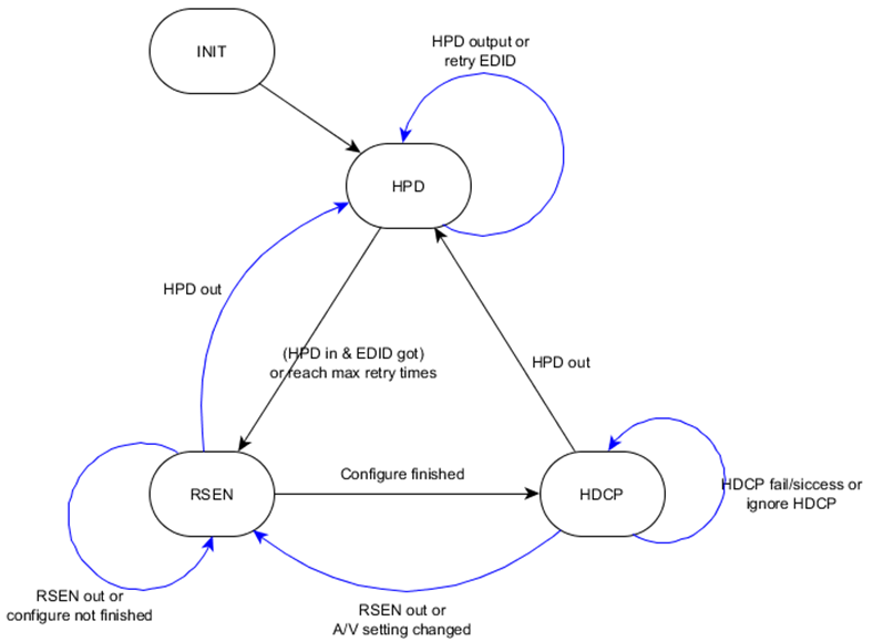
Figure 1920-6 HDMI TX main flow state control
...
20.10 HDMI Interrupts
There are many interrupt events can trigger HDMI TX interrupt. Read Group 383.4 INTR0_STS/383.5 INTR1_STS/383.6 INTR2_STS registers can get the interrupt status. Set corresponding bit to 1 in Group 383.1 INTR0_UNMASK/383.2 INTR1_UNMASK/383.3 INTR2_UNMASK registers can enable the interrupt. Table 1920-2 list each interrupt event.
Interrupt status register | Bit | Event |
INTR0_STS | 0 | Hot Plug change detect |
1 | HDMI RX sense change detect | |
2 | Tclk frequency change detect | |
3 | Every Vsync occurs | |
4 | CEC interrupt, refer to "CEC_STS2" | |
9 | CTS value changed detect | |
10 | Audio FIFO empty | |
11 | Audio FIFO full | |
12 | SPDIF preamble error (reserved) | |
113 | SPDIF sample drop (reserved) | |
14 | SPDIF bi-phase error (reserved) | |
15 | SPDIF parity error (reserved) | |
INTR1_STS | 0 | Every 128 HDCP frames |
1 | Every 16 HDCP frames | |
2 | DDC FIFO full | |
3 | DDC FIFO empty | |
4 | Auto Ri check fail @ frame0 | |
5 | Auto Ri check fail @ frame127 | |
6 | TX Ri does not change between frame0 and frame127 | |
7 | Ri/Pj is not read within one frame or DDC bus error | |
8 | Auto Pj check fail @ frame15 | |
9 | TX Pj does not change between frame0 and frame15 | |
INTR2_STS | 0~15 | Reserved |
Table 1920-1 HDMI TX Interrupt Event
...
20.11 Registers Map
...
20.11.1 Registers Memory Map
Address | Group No. | Register Name | Description |
|---|---|---|---|
0x9C00BE00 | G380.0 | VENDOR ID -- 0x0 | VENDOR ID |
0x9C00BE04 | G380.1 | DEVICE ID -- 0x1 | DEVICE ID |
0x9C00BE08 | G380.2 | Revision -- 0x2 | Revision |
0x9C00BE0C | G380.3 | RESERVED 0003 -- 0x3 | RESERVED 0003 |
0x9C00BE10 | G380.4 | RESERVED 0004 -- 0x4 | RESERVED 0003 |
0x9C00BE14 | G380.5 | PWR CTRL -- 0x5 | PWR CTRL |
0x9C00BE18 | G380.6 | SW RESET -- 0x6 | SW RESET |
0x9C00BE1C | G380.7 | SYSTEM STATUS 0x7 | SYSTEM STATUS |
0x9C00BE20 | G380.8 | SYSTEM CTRL1 -- 0x8 | SYSTEM CTRL1 |
0x9C00BE24 | G380.9 | RESERVED 0009 -- 0x9 | RESERVED 0009 |
0x9C00BE28 | G380.10 | SYSTEM CTRL2 -- 0xa | SYSTEM CTRL2 |
0x9C00BE2C | G380.11 | SYSTEM CTRL3 -- 0xb | SYSTEM CTRL3 |
0x9C00BE30 | G380.12 | SYSTEM CTRL4 -- 0xc | SYSTEM CTRL4 |
0x9C00BE34 | G380.13 | RESERVED 000D -- 0xd | RESERVED 000D |
0x9C00BE38 | G380.14 | RESERVED 000E -- 0xe | RESERVED 000E |
0x9C00BE3C | G380.15 | SYSTEM CTRL5 -- 0xf | SYSTEM CTRL5 |
0x9C00BE40 | G380.16 | HDCP CTRL1 -- 0x10 | HDCP CTRL1 |
0x9C00BE44 | G380.17 | BKSV12 -- 0x11 | BKSV12 |
0x9C00BE48 | G380.18 | BKSV34 -- 0x12 | BKSV34 |
0x9C00BE4C | G380.19 | BKSV5 -- 0x13 | BKSV5 |
0x9C00BE50 | G380.20 | Mi12 -- 0x14 | Mi12 |
0x9C00BE54 | G380.21 | Mi23 -- 0x15 | Mi23 |
0x9C00BE58 | G380.22 | Mi56 -- 0x16 | Mi56 |
0x9C00BE5C | G380.23 | Mi78 -- 0x17 | Mi78 |
0x9C00BE60 | G380.24 | AKSV12 -- 0x18 | AKSV12 |
0x9C00BE64 | G380.25 | AKSV23 -- 0x19 | AKSV23 |
0x9C00BE68 | G380.26 | AKSV5 -- 0x1a | AKSV5 |
0x9C00BE6C | G380.27 | Ri CMP -- 0x1b | Ri CMP |
0x9C00BE70 | G380.28 | Rj CMP -- 0x1c | Rj CMP |
0x9C00BE74 | G380.29 | Ri CMP SET -- 0x1d | Ri CMP SET |
0x9C00BE78 | G380.30 | FrameCnt -- 0x1e | FrameCnt |
0x9C00BE7C | G380.31 | RESERVED 001F -- 0x1f | RESERVED 001F |
...
Address | Group No. | Register Name | Description |
|---|---|---|---|
0x9C00C180 | G387.0 | ISRC2 PB1011 -- 0xe0 | ISRC2 PB1011 |
0x9C00C184 | G387.1 | ISRC2 PB1213 -- 0xe1 | ISRC2 PB1213 |
0x9C00C188 | G387.2 | ISRC2 PB1415 -- 0xe2 | ISRC2 PB1415 |
0x9C00C18C | G387.3 | Gamut Metadata Packet Header --0xe3 | Gamut Metadata Packet Header |
0x9C00C190 | G387.4 | Gamut Metatata Packet PB01 --0xe4 | Gamut Metatata Packet PB01 |
0x9C00C194 | G387.5 | Gamut Metatata Packet PB23 --0xe5 | Gamut Metatata Packet PB23 |
0x9C00C198 | G387.6 | Gamut Metatata Packet PB45 --0xe6 | Gamut Metatata Packet PB45 |
0x9C00C19C | G387.7 | Gamut Metatata Packet PB67 --0xe7 | Gamut Metatata Packet PB67 |
0x9C00C1A0 | G387.8 | Gamut Metatata Packet PB89 --0xe8 | Gamut Metatata Packet PB89 |
0x9C00C1A4 | G387.9 | Gamut Metatata Packet PB1011 --0xe9 | Gamut Metatata Packet PB1011 |
0x9C00C1A8 | G387.10 | Gamut Metatata Packet PB1213 --0xea | Gamut Metatata Packet PB1213 |
0x9C00C1AC | G387.11 | Gamut Metatata Packet PB1415 --0xeb | Gamut Metatata Packet PB1415 |
0x9C00C1B0 | G387.12 | Gamut Metatata Packet PB1617 --0xec | Gamut Metatata Packet PB1617 |
0x9C00C1B4 | G387.13 | Gamut Metatata Packet PB1819 --0xed | Gamut Metatata Packet PB1819 |
0x9C00C1B8 | G387.14 | Gamut Metatata Packet PB2021 --0xee | Gamut Metatata Packet PB2021 |
0x9C00C1BC | G387.15 | Gamut Metatata Packet PB2223 --0xef | Gamut Metatata Packet PB2223 |
0x9C00C1C0 | G387.16 | Gamut Metatata Packet PB2425 --0xf0 | Gamut Metatata Packet PB2425 |
0x9C00C1C4 | G387.17 | Gamut Metatata Packet PB2627 --0xf1 | Gamut Metatata Packet PB2627 |
0x9C00C1C8 | G387.18 | MPEG Source InfoFrame PB01 --0xf2 | MPEG Source InfoFrame PB01 |
0x9C00C1CC | G387.19 | MPEG Source InfoFrame PB23 --0xf3 | MPEG Source InfoFrame PB23 |
0x9C00C1D0 | G387.20 | MPEG Source InfoFrame PB45 --0xf4 | MPEG Source InfoFrame PB45 |
0x9C00C1D4 | G387.21 | MPEG Source InfoFrame PB67 --0xf5 | MPEG Source InfoFrame PB67 |
0x9C00C1D8 | G387.22 | MPEG Source InfoFrame PB89 --0xf6 | MPEG Source InfoFrame PB89 |
0x9C00C1DC | G387.23 | MPEG Source InfoFrame PB10 --0xf7 | MPEG Source InfoFrame PB10 |
0x9C00C1E0 | G387.24 | RESERVED 0718 -- 0xf8 | RESERVED 0718 |
0x9C00C1E4 | G387.25 | RESERVED 0719 -- 0xf9 | RESERVED 0719 |
0x9C00C1E8 | G387.26 | TMDSTX CTRL1 -- 0xfa | TMDSTX CTRL1 |
0x9C00C1EC | G387.27 | TMDSTX CTRL2 -- 0xfb | TMDSTX CTRL2 |
0x9C00C1F0 | G387.28 | TMDSTX CTRL3 -- 0xfc | TMDSTX CTRL3 |
0x9C00C1F4 | G387.29 | TMDSTX CTRL4 -- 0xfd | TMDSTX CTRL4 |
0x9C00C1F8 | G387.30 | TMDSTX CTRL5 -- 0xfe | TMDSTX CTRL5 |
0x9C00C1FC | G387.31 | RESERVED 071F -- 0xff | RESERVED 071F |
...
20.11.2 Registers Description
RGST Table Group 380 HDMI G0
380.0 VENDOR ID ( VENDOR ID -- 0x0 )
Address: 0x9C00BE00
Reset: 0x2401
...