910.1 Introduction
The Timer0 and Timer1 consist of 11-bit down and auto-reload counter driven by a programmable 14-bit pre-scaler. The Timer2 and Timer3 consist of a 16-bit down and auto-reload counter driven by programmable 14-bit or 16-bit pre-scaler. The Timer0/1/2/3 are completely independent and don't share any resource. The Timer0/1 can combine to 22-bit timer; timer2/3 can combine to 32-bit timer. This timer module also include one 20-bit watchdog timer, one 33-bit Standard Timer Counter (STC), one 34-bit Attendance Timer Counter (ATC) and one 24-bit Real Time Counter (RTC).
The control registers locate in RGST table Group12 which memory map to 0x9C000600~0x9C00067F.
...
10.2 Function Diagram
A generalized function diagram of Timer is shown in Figure 910-1.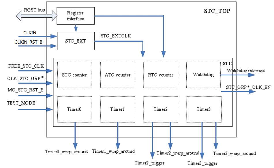
Figure 910-1 Timer Functional Blocks
...
Note: CLKIN = 27MHz for this chip.
...
10.3 Timer0/Timer1 functional description
Figure 910-2 shows the timer0 and timer1 data trigger flow block diagram.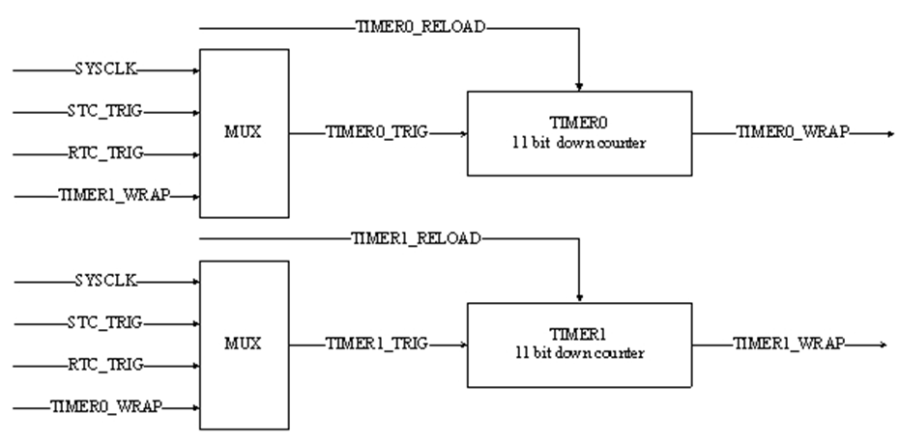
Figure 910-2 Timer0/1 Data Trigger Flow
...
- STC_TRIG: Trigger source of STC counter. When STC pre-scaler counter reaches 0 and trigger in STC pre-scaler asserts, the signal will be asserted for a system cycle, then sent to STC/ATC counter, RTC pre-scaler and watchdog counter as trigger. The signal is registered output.
- RTC_TRIG: Trigger source of RTC counter. When RTC pre-scaler counter reaches 0 and trigger (STC_TRIG) in RTC pre-scaler asserts, the signal will be asserted for a system cycle, then sent to RTC counter as trigger. The signal is registered output.
- SYSCLK: System clock source.
- TIMER0_WRAP: Timer0 wrap-around signal.
- TIMER1_WRAP: Timer1 wrap-around signal.
...
10.3.1 Time Base Operation
The 2 timers provide an 11-bit down-counter. When enable, it will down-count with a reference timing signal selecting from appropriate inputs (Refer to RGST table Group 12.8 timer0_ctl and Group 12.10 timer1_ctl registers). The interrupt will be asserted a pulse (a system clock cycle) if timer0/1 counter TIMER0_CNT/ TIMER1_CNT (Refer to RGST table Group 12.9 timer0_cnt and Group 12.11 timer1_cnt registers) reaches 0 and trigger asserts.
...
10.3.2 Repeat mode and One Shot mode
When timer0/1 counter reaches 0, the reload value (Refer to RGST table Group 12.30 timer0_reload and Group 12.31 timer1_reload registers) will be loaded into timer0/1 counter with repeat mode. RGST table Group 12.8 timer0_ctl bit13 set 1 as repeat mode. RGST table Group 12.10 timer1_ctl bit13 set 1 as repeat mode.
The 2 timers also provide one shot operation when RGST table Group 12.8 timer0_ctl and Group 12.10 timer1_ctl bit13 set 0. In this mode, timer will stop and clear GO flag (bit-11) automatically when the timer0/1 counter reaches 0.
When timer 0/1 reload value (TIME0_RELOAD/TIME1_RELOAD in waveform) changes, which the timer 0/1 counter will not respond to the change immediately until timer0/1 counter reaches 0. Please refer to the figure 910-3.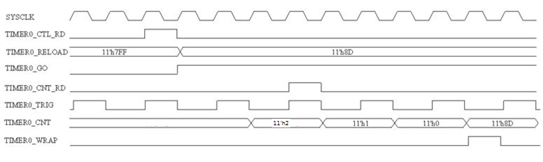
Figure 910-3 Timer0/Timer1 Counter Repeat Mode Timing Diagram
Note: Timer0/1 counter support dynamic read/write. When Timer0/1 counter setting is change, the counter will decrease from the new setting.
...
10.3.3 Timer Trigger Source
The RGST table Group 12.8 timer0_ctl bit[15:14] can select timer0 trigger source. Set 0 is selected SYSCLK, set 1 is selected STC_TRIG, set 2 is selected RTC_TRIG and set 3 is selected TIMER1_WRAP. The cooresponding function control bit of timer1 is Group 12.10 timer1_ctl bit[15:14].
...
10.3.4 22-bit counter mode
The Timer0/1 can combine to 22-bit counter. For example, set timer0 trigger source as SYSCLK and set timer1 trigger source as TIMER0_WRAP, then the timer0+timer1 become a 22-bit counter. When tm0_count reaches 0, it will trigger TIMER0_WRAP to let tm1_count down count and timer0_reload will be reloaded into tm0_count at the same time. Repeat this action, finally the timer0+timer1 will operate like a 22-bit counter.
...
10.3.5 Pause mode
When paused state, timer0/1 counter operation will be disabling and all timer0/1 counter value will be kept. Set RGST table Group 12.8 timer0_ctl bit11 as 0 to come in timer0 pause state. Set RGST table Group 12.10 timer1_ctl bit11 as 0 to come in timer1 pause state.
...
10.4 Timer2/Timer3 functional description
Figure 910-4 shows the timer2 and timer3 data trigger flow block diagram.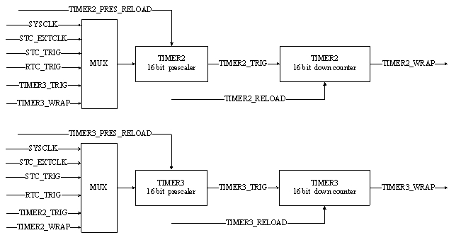
Figure 910-4 Timer2/3 Data Trigger Flow
- STC_TRIG: Trigger source of STC counter. When STC pre-scaler counter reaches 0 and trigger in STC pre-scaler asserts, the signal will be asserted for a system cycle, then sent to STC/ATC counter, RTC pre-scaler and watchdog counter as trigger. The signal is registered output.
- RTC_TRIG: Trigger source of RTC counter. When RTC pre-scaler counter reaches 0 and trigger (STC_TRIG) in RTC pre-scaler asserts, the signal will be asserted for a system cycle, then sent to RTC counter as trigger. The signal is registered output.
- SYSCLK: System clock source.
- STC_EXTCLK: External clock.
- TIMER2_WRAP: Timer2 wrap-around signal.
- TIMER3_WRAP: Timer3 wrap-around signal.
...
10.4.1 Time Base Operation
The 2 timers provide an 16-bit down-counter. When enable, it will down-count with a reference timing signal selecting from appropriate inputs (Refer to RGST table Group 12.16 timer2_ctl and Group 12.20 timer3_ctl registers). The interrupt will be asserted a pulse (a system clock cycle) if timer2/3 counter TIMER2_CNT/ TIMER3_CNT (Refer to RGST table Group 12.19 timer2_cnt and Group 12.23 timer3_cnt registers) reaches 0 and trigger asserts.
...
10.4.2 Repeat mode and One Shot mode
When timer2/3 counter reaches 0, the reload value (Refer to RGST table Group 12.18 timer2_reload and Group 12.22 timer3_reload registers) will be loaded into timer2/3 counter with repeat mode. RGST table Group 12.16 timer2_ctl bit1 set 1 as timer2 repeat mode. RGST table Group 12.20 timer3_ctl bit1 set 1 as timer3 repeat mode.
The 2 timers also provide one shot operation when RGST table Group 12.16 timer2_ctl and Group 12.20 timer3_ctl bit1 set 0. In this mode, timer will stop and clear GO flag (bit-0) automatically when the timer2/3 counter reaches 0.
When timer 2/3 reload value (TIME2_RELOAD/TIME3_RELOAD in waveform) changes, which the timer 2/3 counter will not respond to the change immediately until timer2/3 counter reaches 0..
Note: Timer2/3 counter support dynamic read/write. When Timer2/3 counter setting is change, the counter will decrease from the new setting.
...
10.4.3 Timer Trigger Source
The RGST table Group 12.16 timer2_ctl bit[5:2] can select timer2 trigger source. Set 0 is selected SYSCLK, set 1 is selected STC_TRIG, set 2 is selected RTC_TRIG, set 3 is selected external clock, set 4 is selected TIMER3_TRIG and set 5 is selected TIMER3_WRAP. The cooresponding function control bit of timer1 is Group 12.20 timer3_ctl bit[5:2].
...
10.4.4 32-bit counter mode
The Timer2/3 can combine to 32-bit counter. For example, set timer2 trigger source as SYSCLK and set timer3 trigger source as TIMER2_WRAP, then the timer2+timer3 become a 32-bit counter. When tm2_count reaches 0, it will trigger TIMER2_WRAP to let tm3_count down count and timer2_reload will be reloaded into tm2_count at the same time. Repeat this action, finally the timer2+timer3 will operate like a 32-bit counter.
...
10.4.5 Pause mode
When paused state, timer2/3 counter operation will be disabling and all timer2/3 counter value will be kept. Set RGST table Group 12.16 timer2_ctl bit0 as 0 to come in timer2 pause state. Set RGST table Group 12.20 timer3_ctl bit0 as 0 to come in timer3 pause state.
...
10.4.6 Pre-scaling function
The Timer2/3 can set 16-bit pre-scaling value in RGST table Group 12.17 timer2_pres_value and Group 12.21 timer3_pres_value. The specified clock source is divided by this pre-scaler to generate trigger of the Timer2/3 counter. The relationship of CLK_timer2 and CLK_src is CLK_timer2 = CLK_src / (timer2_prescaler+1). Timer3 have the same formula.
...
10.5 STC/ATC/RTC/Watchdog
Figure 910-5 shows the data flow of STC/ATC/RTC/Watchdog.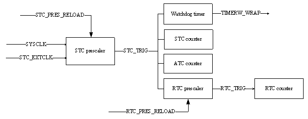
Figure 910-5 STC/ATC/RTC/Watchdog data flow
...
10.5.1 STC Pre-scaler And Counter
STC (Standard Timer Counter) is a 14-bit pre-scaler counter. As Figure 17-5, STC pre-scaler will divide the SYSCLK or STC_EXTCLK then generate STC_TRIG signal.
In the applications, STC_TRIG usually is a 90 kHz signal. STC Counter will increase after trigger by STC_TRIG. This is the outline of the STC counter working mode. The paragraph follows will explain the pre-scaler and counter details.
- STC pre-scaler: When pre-scaler reload value changed (STC_PRES_RELOAD in the figure), pre-scaler counter will clean to 0 right now. The divider relation is STC_TRIG = SYSCLK / (stc_prescaler+1).
- STC counter: It is a 32-bit width counter. It will increase by STC_TRIG trigger. When the counter count to the max value, if STC_TRIG come again, which action will cause overflow. The STC counter support dynamic read/write, but the value maybe not precise. So for read operation add latch-read mode. The STC counter value is latched when CPU write any value to Group 12.26 stcl_2 bit32.
...
10.5.2 ATC Counter
ATC (Attendance Timer Counter) is a 34-bitwidth counter; it will increase by STC_TRIG trigger. When the counter count to the max value and STC_TRIG come again, the action will cause overflow. The count value registers are Group 12.27~29. This also support dynamic read/write like STC counter
...
10.5.3 RTC Pre-scaler And Counter
RTC (Real Time Counter) is a 14-bit width counter. RTC Pre-scaler trigger source is STC_TRIG. It is different trigger source with STC Pre-scaler/Counter. And RTC counter doesn't support latch-read mode, other feature is the same with STC Pre-scaler/Counter
...
10.5.4 Watchdog Counter
This is a 20-bit width counter. On unpause state (setting by command, reference the register file, default is pause), the counter will decrease when STC_TRIG trigger. The firmware can read/write the higher 16-bit of counter by Group 12.13 timerw_cnt register. Watchdog counter controlled by command which in the Group 12.12 timerw_ctl register. Use the watchdog timer to monitor the firmware behaves. Hardware will remember the command written by software. The watchdog will be paused and unlocked state after system reset. Below lists the watchdog commands.
...
Be careful, when the counter decrease to 0, the interrupt will be set until the related commands be executed then clear interrupt. And the counter value will reload to the max value on next STC_TRIG trigger.
...
10.6 Timer Interrupts
- STC_INTERRUPT_TIMERW: Watchdog interrupt flag. When watchdog counter reaches 0, the interrupt will be asserted immediately until software clear (set timerw_ctl register to 0x7482).
- STC_INTERRUPT_TIMER0: Timer0 wrap-around interrupt flag. When timer0 counter reaches 0 and trigger in timer0 asserts, the interrupt will be asserted a pulse with a system cycle, registered output.
- STC_INTERRUPT_TIMER1: Timer1 wrap-around interrupt. When timer1 counter reaches 0 and trigger in timer1 asserts, the interrupt will be asserted a pulse with a system cycle, registered output.
- STC_INTERRUPT_TIMER2A: Timer2 trigger interrupt. Registered output, from timer2 pre-scaler. When timer2 pre-scaler counter reaches 0 and pre-trigger in pre-scaler asserts, the trigger interrupt will be asserted a pulse with a system cycle, then sent to timer2 down counter as trigger source.
- STC_INTERRUPT_TIMER2B: Timer2 wrap-around interrupt. When timer2 down counter reaches 0 and trigger (STC_INTERRUPT_TIMER2A) asserts, the interrupt will be asserted a pulse with a system cycle, registered output.
- STC_INTERRUPT_TIMER3A: Timer3 trigger interrupt. Registered output, from timer3 pre-scaler. When timer3 pre-scaler counter reaches 0 and pre_trigger in pre-scaler asserts, the trigger interrupt will be asserted a pulse with a system cycle, then sent to timer3 down counter as trigger source.
- STC_INTERRUPT_TIMER3B: Timer3 wrap-around interrupt. When timer3 down counter reaches 0 and trigger (STC_INTERRUPT_TIMER3A) asserts, the interrupt will be asserted a pulse with a system cycle, registered output.
| Anchor | ||||
|---|---|---|---|---|
|
...
10.7 Registers Map
...
10.7.1 Registers Memory Map
Address | Group No. | Register Name | Description |
|---|---|---|---|
0x9C000600 | G12.0 | stc_15_0 | STC Counter Register |
0x9C000604 | G12.1 | stc_31_16 | STC Counter Register |
0x9C000608 | G12.2 | stc_32 | STC Counter Register |
0x9C00060C | G12.3 | stc_divisor | STC pre-scaling Register |
0x9C000610 | G12.4 | rtc_15_0 | RTC Counter Register |
0x9C000614 | G12.5 | rtc_23_16 | RTC Counter Register |
0x9C000618 | G12.6 | rtc_divisor | RTC Divider Register |
0x9C00061C | G12.7 | stc_config | External reference clock divisor |
0x9C000620 | G12.8 | timer0_ctl | Timer0 Control Register |
0x9C000624 | G12.9 | timer0_cnt | Timer0 Counter Register |
0x9C000628 | G12.10 | timer1_ctl | Timer1 Control Register |
0x9C00062C | G12.11 | timer1_cnt | Timer1 Counter Register |
0x9C000630 | G12.12 | timerw_ctl | Watchdog Timer Control register |
0x9C000634 | G12.13 | timerw_cnt | Watchdog Timer Counter register |
0x9C000638 | G12.14 | stc 47 32 | STC Counter Register |
0x9C00063C | G12.15 | stc 63 48 | STC Counter Register |
0x9C000640 | G12.16 | timer2_ctl | Timer2 Control Register |
0x9C000644 | G12.17 | timer2_pres_value | Timer2 16-bit pre-scaling value |
0x9C000648 | G12.18 | timer2 reload | Timer2 16-bit reload value |
0x9C00064C | G12.19 | timer2_cnt | Timer2 16-bit counter value |
0x9C000650 | G12.20 | timer3_ctl | Timer3 Control Register |
0x9C000654 | G12.21 | timer3_pres_value | Timer3 16-bit pre-scaling value |
0x9C000658 | G12.22 | timer3_reload | Timer3 16-bit reload value |
0x9C00065C | G12.23 | timer3_cnt | Timer3 16-bit counter value |
0x9C000660 | G12.24 | stcl_0 | Latched value (bit 15:0) of STC counter |
0x9C000664 | G12.25 | stcl_1 | Latched value (bit 31:16) of STC counter |
0x9C000668 | G12.26 | stcl_2 | Latched value (bit 32) of STC counter |
0x9C00066C | G12.27 | atc_0 | 34 bit ATC counter [15:0] |
0x9C000670 | G12.28 | atc_1 | 34 bit ATC counter [31:16] |
0x9C000674 | G12.29 | atc_2 | 34 bit ATC counter [33:32] |
0x9C000678 | G12.30 | timer0 reload | Timer0 16-bit reload value |
0x9C00067C | G12.31 | Timer1 reload | Timer1 16-bit reload value |
...
10.7.2 Registers Description
RGST Table Group 12 STC
12.0 STC Counter Register (stc 15 0)
Address: 0x9C000600
Reset: 0x0001
...