14.1 Introduction
Ethernet is a computer local area network technology. IEEE's IEEE 802.3 standard sets the technical standard for Ethernet, which specifies the content of the connection, electronic signal and medium access layer agreements including the physical layer. Ethernet is the most popular area network technology currently used, replacing other regional network standards such as Token Ring, FDDI and ARCNET. The standard topology of Ethernet is a bus topology, but the current fast Ethernet (100BASE-T, 1000BASE-T standard) used switch/hub in network connection and organization to increase the network speed, use efficiency and minimize conflicts. As a result, the topology of the Ethernet network becomes a star topology.
Ethernet implements the idea of transmitting information to multiple nodes in the radio system on the network. Each node must obtain cables or channels to transmit information. Each node has a globally unique 48-bit address, which is the MAC address assigned by the manufacturer to the network cardNetwork Interface Card (NIC). The MAC address is used to ensure that all nodes on the Ethernet can authenticate each other. Because Ethernet is so common, many manufacturers integrate Ethernet cards directly into their motherboards.
This section describes the Ethernet Switch and its associated operational modes. The SP7021 Ethernet is supports a layer 2 (L2) switch (L2SW) with 2 Ethernet ports and 1 SoC port (also called CPU port or NIC port) which acts as like a NIC card connected to the 3rd port of switch. The base address for Ethernet Switch Control and Status Registers (CSR) is 0x9C108000 and all registers in the memory map address ranges from 0x9C108000 to 0x9C10827F.
Table 14-1. shows the key feature of Ethernet hardware (L2SW IP) of SP7021.
switch ports |
|
VLAN |
|
Address table |
|
QoS |
|
LED |
|
Data buffer |
|
System interface |
|
Table 14-1. Key feature of Ethernet Switch (L2SW IP) of SP7021
...
14.3.1 Descriptors of Ethernet
Ethernet hardware The Layer 2 Switch (L2SW IP) uses descriptors to control transmission and reception of packets between CPU interface and L2 switch hardware2 Ethernet ports. Software allocates and initializes memory for descriptors. Descriptors consists of many fields which instructs Ethernet hardware where and how to get or store data for transmission and reception. The Ethernet hardware reads descriptors and uses the allocated memory to access data. Descriptors should be allocated continuously in the memory by software called descriptor queue and the Ethernet hardware uses these descriptors in order. Figure 14-2 illustrates the operation of descriptorsrelationship between descriptors and data buffers.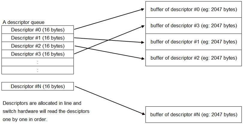
Figure 14-2 Descriptors of L2SW
...