15. Ethernet Switch
- edwin.chiu (Unlicensed)
- Michael Su (Unlicensed)
15.1 Introduction
Ethernet is a computer local area network technology. IEEE's IEEE 802.3 standard sets the technical standard for Ethernet, which specifies the content of the connection, electronic signal and medium access layer agreements including the physical layer. Ethernet is the most popular area network technology currently used, replacing other regional network standards such as Token Ring, FDDI and ARCNET. The standard topology of Ethernet is a bus topology, but the current fast Ethernet (100BASE-T, 1000BASE-T standard) used switch/hub in network connection and organization to increase the network speed, use efficiency and minimize conflicts. As a result, the topology of the Ethernet network becomes a star topology.
Ethernet implements the idea of transmitting information to multiple nodes in the radio system on the network. Each node must obtain cables or channels to transmit information. Each node has a globally unique 48-bit address, which is the MAC address assigned by the manufacturer to the Network Interface Card (NIC). The MAC address is used to ensure that all nodes on the Ethernet can authenticate each other. Because Ethernet is so common, many manufacturers integrate Ethernet cards directly into their motherboards.
This section describes the Ethernet Switch and its associated operational modes. The SP7021 supports a layer 2 (L2) switch (L2SW) with 2 Ethernet ports and 1 SoC port (also called CPU port or NIC port) which acts like a NIC card connected to the 3rd port of switch. The base address for Ethernet Switch Control and Status Registers (CSR) is 0x9C108000 and all registers in the memory map address ranges from 0x9C108000 to 0x9C10827F.
Table 15-1. shows the key feature of Ethernet hardware (L2SW IP) of SP7021.
switch ports |
|
VLAN |
|
Address table |
|
QoS |
|
LED |
|
Data buffer |
|
System interface |
|
Table 15-1. Key feature of Ethernet Switch (L2SW IP) of SP7021
15.2 Function Diagram
A generalized function diagram of Ethernet L2SW of SP7021 is shown in Figure 15-1.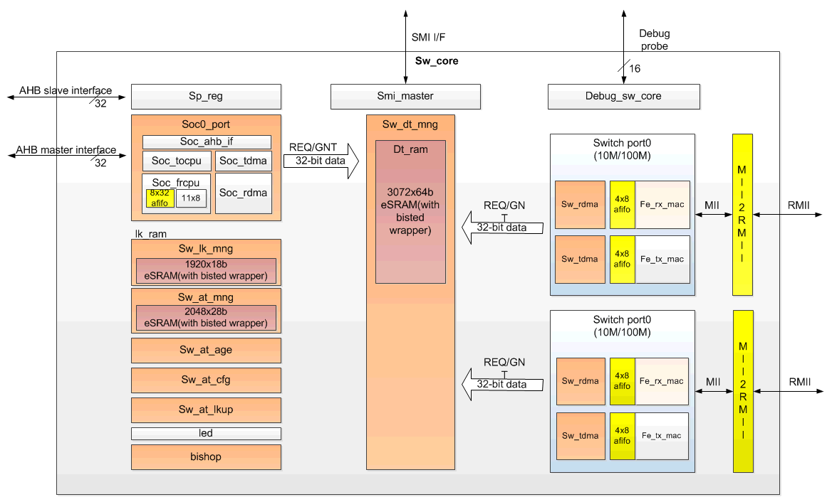
Figure 15-1 Ethernet Switch (L2SW IP) Block Diagram
Here are descriptions of each block:
- sw_port: Switch port0/port1. 10M/100M Ethernet port transceiver.
- sw_dt_mng: Switch data buffer manager.
- soc_port: Soc port, CPU can receive packet from or transmit packet to switch through this port.
- sw_lk_mng: Link manager. It schedules the packet transmit and receive for port0/port1/soc port.
- sw_at_mng: Address table manager. It controls the address table learning and searching.
- sw_at_age: Address table aging control.
- sw_at_cfg: Address table configuration by CPU.
- sw_at_lkup: Address table lookup by CPU.
- Led: LED control. 3 LED for each port.
- bishop: Memory BIST control.
- sp_reg: Switch register file.
- smi_master: Serial management interface master. Switch can polling Ethernet PHY registers through SMI interface.
- Debug_sw_core: Debug control. 16 bits debug probe are provided for debug purpose.
15.3 Data Structure
15.3.1 Descriptors of Ethernet
The Layer 2 Switch (L2SW) uses descriptors to control transmission and reception of packets between CPU interface and 2 Ethernet ports. Software allocates and initializes memory for descriptors. Descriptors consists of many fields which instructs Ethernet hardware where and how to get or store data for transmission and reception. The Ethernet hardware reads descriptors and uses the allocated memory to access data. Descriptors should be allocated continuously in the memory by software called descriptor queue and the Ethernet hardware uses these descriptors in order. Figure 15-2 illustrates the relationship between descriptors and data buffers.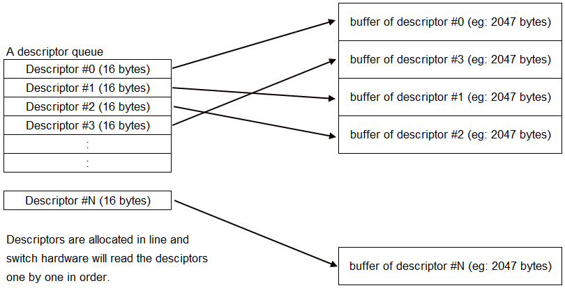
Figure 15-2 Descriptors of L2SW
15.3.2 TX Descriptor
Ethernet hardware supports 2 descriptors queue for transmission and 2 descriptors queue for reception. One descriptor queue is for low-priority packets and the other is for high-priority packets. Packets with high-priority tagged will be received and placed on high-priority queue and other packets will be received and placed on low-priority queue during reception. For transmission, software decides which queue the packets will be placed in. Figure 15-3 shows the detailed field definition of transmission (TX) descriptor.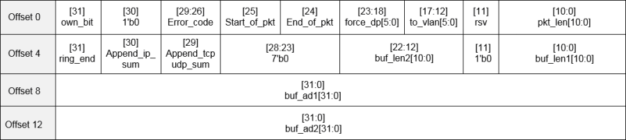
Figure 15-3 Field definition of TX descriptor
Here are detailed description of each field:
- own_bit:
0: The descriptor is owned by software. The Ethernet hardware sets own-bit to 0 when transmission is done or error happens.
1: The descriptor is owned by Ethernet hardware. Software sets own-bit to 1 when a descriptor is ready for Ethernet hardware fetching.
- error_code:
- start_of_pkt:
1: The first descriptor of the packet;
0: The middle/last descriptor of the packet.
- end_of_pkt:
1: The last descriptor of the packet;
0: The middle/first descriptor of the packet.
- force_dp: force destination port
[18]: force forward to port 0
[19]: force forward to port 1
- to_vlan: the vlan member set index, the packet forward to the designated VLAN group.
- pkt_length: tx_len_r, the length of the current packet
- ring_end: end of the descriptor ring
- append_ip_sum: append IP checksum
- append_tcpudp_sum: append tcp/udp checksum (not implemented yet)
- buf2_length: buf2 length. Each descriptor can support two buffers, if the tx_length > buf1_length, then get the rest data from buf2.
- buf1_length: buf1 length.
- buf1_addr: buf1 address.
- buf2_addr: buf2 address.
15.3.3 RX Descriptor
Figure 15-4 shows the detailed field definition of reception (RX) descriptor.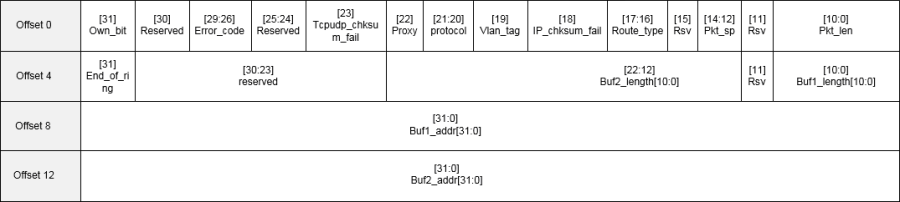
Figure 15-4 Field definition of RX descriptor
Here are detailed description of each field:
- own_bit:
0: The descriptor is owned by software. The Ethernet hardware sets own-bit to 0 when receiving is done or error.
1: The descriptor is owned by Ethernet hardware. Software sets own-bit to 1 when a descriptor is ready for Ethernet hardware fetching.
- error_code:
- tcpudp_chksum_fail: (not implemented yet)
1: The tcp/udp frame checksum error.
0: The tcp/udp frame checksum ok.
- proxy:
1:The mac address of soc port has been learned into the Address Table when switch transmit the packet to soc port.
0:The mac address of soc port hasn't been learned into the Address Table while switch transmit the packet to soc port.
- protocol:
00: IPv4 packet
01: PPPoE packet
- others: reserved
- vlan_tag:
1: VLAN tagged frame
0: non VLAN tagged frame
- ip_chksum_fail:
1: The IP frame checksum error
0: The IP frame checksum ok.
- route_type:
00: UC
01: MC
10: BC
11: RMC
- pkt_sp:
000: from port0
001: from port1
110: soc0 loopback
101: soc1 loopback
- Others: reserved
- pkt_lenth: length of current packet
- ring_end: end of the descriptor ring
- buf2_length: buf2 length. Each descriptor can support two buffers, if the rx_len_r > buf1_length, then put the rest data to buf2.
- buf1_length: buf1 length.
- buf1_addr: buf1 address.
- buf2_addr: buf2 address.
15.4 Ethernet Switch Function with Address Table
The switch used in the Ethernet network can increase the available bandwidth of the network, and can also analyze the MAC address of the source end and the destination end according to the sent network packet, and create a MAC address table, and the network packet is correctly forwarded by such a MAC address table.
Although the switch is the second layer operating in the network seven-layer architecture, due to the switch has a higher speed internal structure and a larger number of interfaces, so it can provide more network traffic compared with the traditional gateway.
Regarding the learning of MAC addresses, the switch will listen to the incoming frames from their peers (called the Frame through the network packet of the switch), detect the source MAC address of these data, and recorded the correspondence of the MAC address and port number in the local MAC database. This MAC database is usually called MAC Address Table.
When the switch receives the Frame again, it will first go to the MAC database to see which node to go to the machine specified by the destination MAC address. If the destination MAC address can be found in the MAC database, then This Frame will only be forwarded from the learned port. If such a correspondence is not found in the MAC database, the Frame will be forwarded from all other ports (except sources).
SP7021 can supports up to 1K MAC address table entries. Figure 15-5 shows the address table format. 
Figure 15-5 Field definition of address table
Here are detailed description of each field:
- mc_ingr – enable checking the destined port and local port are in the same group for reserved MC.
- Proxy - a packet from CPU port (SoC Port or called Port 3)
- Look up the address table. If the SA is (cpu port=0 or proxy =1)
- Add or update proxy 1 when learning.
- When LAN port receiving a packet.
- Look up the address table.
- If the DA (proxy bit ==1), then add a proxy bit ==1 to link table.
- AHB port transmitting a packet to Port3 will add a proxy bit to descriptor.
- Age – aging bit – The field will be 001 when a valid address is learned. It will increase by one. Once the 60 sec counter pulse is reached. When the field = 110 and the 60 sec counter pulse comes, it will wrap to 000 and the address will be aged out.
- Vid_index – VLAN member set index field.
- soc0_port – the learned port is soc0 port
- soc1_port – the learned port is soc1 port
- Reserved for further usage
- Port map – the learned port bit map.
- MAC [38:0] – the MAC address.
15.5 Three Operation Modes
Ethernet driver of SP-7021 supports 3 operation modes:
- An NIC with daisy-chain mode
- Dual NIC mode
- An NIC with daisy-chain mode 2
In "An NIC with daisy-chain mode", Ethernet driver creates one net-device interface (ex: eth0). The net-device interface is connected to two LAN ports (two RJ45 sockets) via L2 switch. In this mode, a packet from one LAN port will be either forwarded to net-device interface (eht0) if its destination address matches MAC address of net-device interface (eth0), or forwarded to other LAN port. A packet from net-device interface (eth0) will be forwarded to a LAN port if its destination address is learnt by L2 switch, or forwarded to both LAN ports if its destination has not been learnt yet. Figure 15-6 illustrates the packets flow in this mode.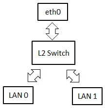
Figure 15-6 Packets flow in "An NIC with daisy-chain" mode
In "Dual NIC mode", Ethernet driver creates two net-device interfaces (ex: eth0 and eth1). Each has its dedicated LAN port. Packets will not be forwarded between two ports, unless you run some bridge utilities manually. Refer to Figure 15-7, packets from eth0 will be always forwarded to LAN port 0 and packets from LAN port 0 will be always forwarded to eth0. The same theory is applied for eth1 and LAN port 1.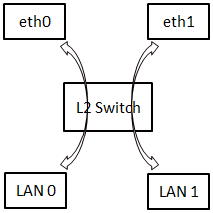
Figure 15-7 Packets flow in "Dual NIC" mode
"An NIC with daisy-chain mode 2" is similar to "An NIC with daisy-chain mode". The difference is that a packet from net-device interface (eth0) will be always forwarded to both LAN ports. Learning function of L2 switch is turned off in this mode. This means L2 switch will never learn the source address of a packet. So, it always forward packets to both LAN ports. This mode works like you have 2-port Ethernet hub.
15.6 L2SW Interrupts
The L2SW interrupt events are connected to the same interrupt vector, please refer to figure 15-8. These events generate an interrupt if the corresponding "Enable Control Bit" is set. The detail L2SW interrupt information refer to Ethernet Group0.0 sw_int_status_0 register for port0 and Group0.52 sw_int_status_1 register for port1. The enable register is Ethernet Group0.0 sw_int_mask_0 register for port0 and Group0.53 sw_int_mask_1 register for port1.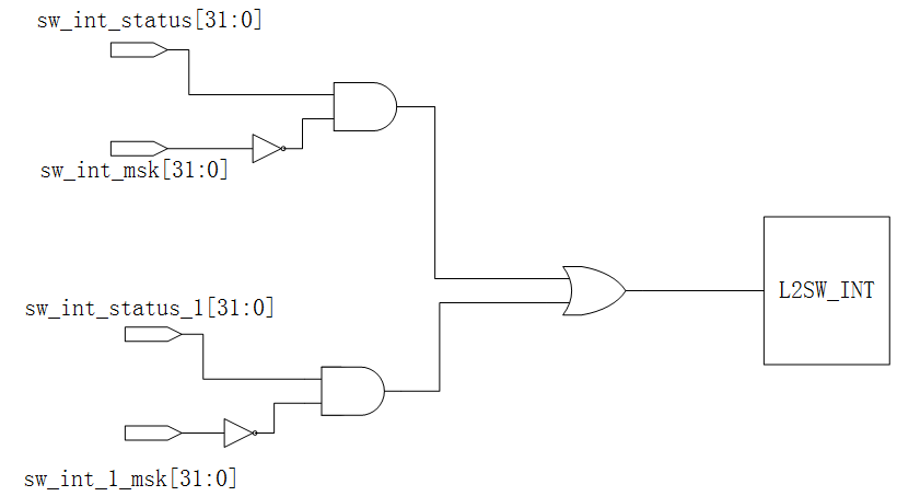
Figure 15-8 L2SW Interrupt Tree
Table 15-2/15-3 shows the Group0.0 sw_int_status_0/Group0.52 sw_int_status_1 registers for each interrupt flag description.
Fields | Fields name | Description |
Bit 31 | daisy_mode_chg | Daisy mode change flag |
Bit 23 | appending_error_0 | IP checksum append error |
Bit 22 | Watchdog1_tmr_expired | Watchdog1_tmr_expired |
Bit 21 | Watchdog0_tmr_expired | Watchdog0_tmr_expired |
Bit 20 | has_intruder | Intruder alert |
Bit 19 | port_st_chg | Port status change |
Bit 18 | bc_storm | BC storm |
Bit 17 | must_drop_lan | Global queue exhausted The must_drop_set_th refer to register Group0.47 flow_ctrl_th3[11:8]. |
Bit 16 | global_que_full | Global queue full (refer to register Group0.2 fl_cntl_th[23:16]). |
Bit 15 | soc_tx_pause_on_0 | Soc port0 transmit pause on |
Bit 14 | soc_qfull_0 | Soc port0 out queue full (Refer to register Group0.3 cpu_fl_cntl_th[15:8]). |
Bit 9 | lan_que_full[1] | port1 out queue full (Refer to register Group0.3 cpu_fl_cntl_th[7:0]). |
Bit 8 | lan_que_full[0] | port0 out queue full (Refer to register Group0.3 cpu_fl_cntl_th[7:0]). |
Bit 7 | L_desc_full_0 | Low priority descriptor full for soc port0 |
Bit 6 | H_desc_full_0 | High priority descriptor full for soc port0 |
Bit 5 | Rx_l_done_0 | Receive low priority descriptor done for soc port0 |
Bit 4 | Rx_h_done_0 | Receive high priority descriptor done for soc port0 |
Bit 3 | Tx_l_done_0 | Transmit low priority descriptor done for soc port0 |
Bit 2 | Tx_h_done_0 | Transmit high priority descriptor done for soc port0 |
Bit 1 | Tx_desc_err_sa_0 | TX descriptor error for soc port0 |
Bit 0 | Rx_desc_err_sa_0 | RX descriptor error for soc port0 |
Table 15-2 Group0.0 sw_int_status_0 register.
Fields | Fields name | Description |
Bit 23 | appending_error_1 | IP checksum append error |
Bit 15 | soc_tx_pause_on_1 | Soc port1 transmit pause on |
Bit 14 | soc_qfull_1 | Soc port1 out queue full (Refer to register Group0.3 cpu_fl_cntl_th[15:8]). |
Bit 7 | L_desc_full_1 | Low priority descriptor full for soc port1 |
Bit 6 | H_desc_full_1 | High priority descriptor full for soc port1 |
Bit 5 | Rx_l_done_1 | Receive low priority descriptor done for soc port1 |
Bit 4 | Rx_h_done_1 | Receive high priority descriptor done for soc port1 |
Bit 3 | Tx_l_done_1 | Transmit low priority descriptor done for soc port1 |
Bit 2 | Tx_h_done_1 | Transmit high priority descriptor done for soc port1 |
Bit 1 | Tx_desc_err_sa_1 | TX descriptor error for soc port1 |
Bit 0 | Rx_desc_err_sa_1 | RX descriptor error for soc port1 |
Table 15-3 Group0.52 sw_int_status_1 register.
15.7 Registers Map
15.7.1 Registers Memory Map
| Address | Group No. | Register Name | Description |
|---|---|---|---|
| 0x9C108000 | G0.0 | sw int status 0 | Interrupt Status 0 |
| 0x9C108004 | G0.1 | sw int mask 0 | Interrupt Mask 0 |
| 0x9C108008 | G0.2 | fl cntl th | Flow Control Threshold |
| 0x9C10800C | G0.3 | cpu fl cntl th | CPU Port Flow Control Threshold |
| 0x9C108010 | G0.4 | pri fl cntl | Priority Flow Control |
| 0x9C108014 | G0.5 | vlan pri th | Vlan Priority Threshold |
| 0x9C108018 | G0.6 | En tos bus | TOS Enable |
| 0x9C10801C | G0.7 | TOS map0 | TOS Map 0 |
| 0x9C108020 | G0.8 | TOS map1 | TOS Map 1 |
| 0x9C108024 | G0.9 | TOS map2 | TOS Map 2 |
| 0x9C108028 | G0.11 | TOS map3 | TOS Map 3 |
| 0x9C10802C | G0.11 | TOS map4 | TOS Map 4 |
| 0x9C108030 | G0.12 | TOS map5 | TOS Map 5 |
| 0x9C108034 | G0.13 | TOS map6 | TOS Map 6 |
| 0x9C108038 | G0.14 | TOS map7 | TOS Map 7 |
| 0x9C10803C | G0.15 | global que status | Global Queue Status |
| 0x9C108040 | G0.16 | addr tbl srch | Address Table Search |
| 0x9C108044 | G0.17 | adr tblst | Address Table Status 0 |
| 0x9C108048 | G0.18 | MAC ad ser0 | Address Table Status 1 |
| 0x9C10804C | G0.19 | MAC ad ser1 | Address Table Status 2 |
| 0x9C108050 | G0.21 | wt mac ad0 | wt mac ad0 |
| 0x9C108054 | G0.21 | w mac 15 0 bus | w mac 15 0 bus |
| 0x9C108058 | G0.22 | w mac 47 16 bus | w mac 47 16 bus |
| 0x9C10805C | G0.23 | PVID config0 | PVID configure 0 |
| 0x9C108060 | G0.24 | Reserved | Reserved |
| 0x9C108064 | G0.25 | VLAN member config0 | VLAN member set config 0 |
| 0x9C108068 | G0.26 | VLAN member config1 | VLAN member set config 1 |
| 0x9C10806C | G0.27 | port ability | port ability |
| 0x9C108070 | G0.28 | port st | port status |
| 0x9C108074 | G0.29 | cpu cntl | CPU port control |
| 0x9C108078 | G0.31 | port cntl0 | port control 0 |
| 0x9C10807C | G0.31 | port cntl1 | port control 1 |
| 0x9C108080 | G0.32 | port cntl2 | port control 2 |
| 0x9C108084 | G0.33 | sw glb cntl | switch global control |
| 0x9C108088 | G0.34 | sw reset | Switch Reset |
| 0x9C10808C | G0.35 | led port0 | LED Port 0 |
| 0x9C108090 | G0.36 | led port1 | LED Port 1 |
| 0x9C108094 | G0.37 | Reserved | Reserved |
| 0x9C108098 | G0.38 | Reserved | Reserved |
| 0x9C10809C | G0.39 | Reserved | Reserved |
| 0x9C1080A0 | G0.41 | watch dog trig rst | Watch dog trigger reset |
| 0x9C1080A4 | G0.41 | watch dog stop cpu | Watch dog stop CPU port receiving |
| 0x9C1080A8 | G0.42 | phy cntl reg0 | PHY control register 0 |
| 0x9C1080AC | G0.43 | phy cntl reg1 | PHY control register 1 |
| 0x9C1080B0 | G0.44 | mac force mode | MAC force mode |
| 0x9C1080B4 | G0.45 | VLAN group config0 | VLAN group port config 0 |
| 0x9C1080B8 | G0.46 | Reserved | Reserved |
| 0x9C1080BC | G0.47 | flow ctrl th3 | Flow control threshold |
| 0x9C1080C0 | G0.48 | queue status 0 | Queue status |
| 0x9C1080C4 | G0.49 | debug cntl | Debug control |
| 0x9C1080C8 | G0.51 | Reserved | Reserved |
| 0x9C1080CC | G0.51 | mem test info | Queue status |
| 0x9C1080D0 | G0.52 | sw int status 1 | Interrupt Status 1 |
| 0x9C1080D4 | G0.53 | sw int mask 1 | sw int mask 1 |
| 0x9C1080D8 | G0.54 | sw global signal | Global Control |
| 0x9C1080DC | G0.55 | Reserved | Reserved |
| 0x9C1080E0 | G0.56 | Reserved | Reserved |
| 0x9C1080E4 | G0.57 | Reserved | Reserved |
| 0x9C1080E8 | G0.58 | Reserved | Reserved |
| 0x9C1080EC | G0.59 | Reserved | Reserved |
| 0x9C1080F0 | G0.60 | Reserved | Reserved |
| 0x9C1080F4 | G0.61 | Reserved | Reserved |
| 0x9C1080F8 | G0.62 | Reserved | Reserved |
| 0x9C1080FC | G0.63 | Reserved | Reserved |
| Address | Group No. | Register Name | Description |
|---|---|---|---|
| 0x9C108200 | G0.128 | reserved | Reserved |
| 0x9C108204 | G0.129 | Reserved | Reserved |
| 0x9C108208 | G0.130 | cpu tx trig | CPU transmit trigger demand |
| 0x9C10820C | G0.131 | Tx hbase ad 0 | SoC port0 transmit high level priority descriptor base address |
| 0x9C108210 | G0.132 | Tx lbase ad 0 | SoC port0 transmit low level priority descriptor base address |
| 0x9C108214 | G0.133 | Rx hbase ad 0 | SoC port0 receive high level priority descriptor base address |
| 0x9C108218 | G0.134 | Rx lbase ad 0 | SoC port0 receive low level priority descriptor base address |
| 0x9C10821C | G0.135 | Tx hw ad 0 | SoC port0 transmit high level priority current working descriptor address |
| 0x9C108220 | G0.136 | Tx lw ad 0 | SoC port0 transmit low level priority current working descriptor address |
| 0x9C108224 | G0.137 | Rx hw ad 0 | SoC port0 receive high level priority current working descriptor address |
| 0x9C108228 | G0.138 | Rx lw ad 0 | SoC port0 receive low level priority current working descriptor address |
| 0x9C10822C | G0.139 | cpu port cntl reg 0 | SoC Port0 Control Register |
15.7.2 Registers Description
0.0 Interrupt Status Reg 0 (sw int status 0)
Address: 0x9C108000
Reset: 0x0
| Field Name | Bit | Access | Description |
| daisy mode chg | 31 | W1C | Daisy mode change When entry or exit Daisy mode, this bit will be set. SW can get current mode by polling register port st[31]. |
| reserved | 30:24 | W1C | RESERVED Reserved for further usage. |
| appending error 0 | 23 | W1C | IP Checksum Append Error High active to indicate IP checksum append fail. HW checks the packet data from SoC port 0 and assert this bit to 1 if it is not a IP packet while "append ip sum"(transmit descriptor bit 30)=1. If this bit asserts, it means the trans- mit descriptor is inconsistent with the transmit data. HW will not append checksum for this packets if append- ing error. Write one clear. |
| Watchdog1 tmr expired | 22 | W1C | Watchdog timer1 expired High active to indicate watch dog timer1 expired. Write one clear. |
Watchdog0 tmr expired | 21 | W1C | Watchdog timer0 expired |
has intruder | 20 | W1C | Atruder Alert |
port st chg | 19 | W1C | Port Status Change |
bc storm | 18 | W1C | BC Storm |
must drop lan | 17 | W1C | Global Queue exhausted |
global que full | 16 | W1C | Global queue full |
soc tx pause on 0 | 15 | W1C | Soc port0 transmit pause on |
soc qfull 0 | 14 | W1C | Soc port0 out queue full |
reserved | 13:10 | RO | RESERVED |
lan que full[1] | 9 | W1C | port 1 out queue full |
lan que full[0] | 8 | W1C | port 0 out queue full |
L desc full 0 | 7 | W1C | Low priority descriptor full for soc port0 |
H desc full 0 | 6 | W1C | High priority descriptor full for soc port0 |
Rx l done 0 | 5 | W1C | Receive low priority descriptor done for soc port0 |
Rx h done 0 | 4 | W1C | Receive high priority descriptor done for soc port0 |
Tx l done 0 | 3 | W1C | Transmit low priority descriptor done for soc port0 |
Tx h done 0 | 2 | W1C | Transmit high priority descriptor done for soc port0 |
Tx desc err sa 0 | 1 | W1C | TX descriptor error for soc port0 |
Rx desc err sa 0 | 0 | W1C | RX descriptor error for soc port0 |
0.1 Interrupt Mask Register 0 (sw int mask 0)
Address: 0x9C108004
Reset: 0x80ff c3ff
| Field Name | Bit | Access | Description |
int0 mask 31 | 31 | RW | Interrupt mask |
reserved | 30:24 | RO | RESERVED |
int0 mask 23 14 | 23:14 | RW | Interrupt mask |
reserved | 13:10 | RO | RESERVED |
int0 mask 9 0 | 9:0 | RW | Interrupt mask |
0.2 Flow Control Threshold (fl cntl th)
Address: 0x9C108008
Reset: 0x8878 5a46
| Field Name | Bit | Access | Description |
| Fc rls th | 31:24 | RW | Flow control release threshold Flow control is off when empty global queue block counts is greater than the threshold. |
| Fc set th | 23:16 | RW | Flow control set threshold Flow control is on when the empty global queue block counts is less than the threshold |
| Drop rls th | 15:8 | RW | Drop release threshold Hardware will stop dropping packets when the empty global queue block counts is greater than the threshold. |
| Drop set th | 7:0 | RW | Drop set threshold Hardware will start dropping packets when the empty global queue block counts is less than the threshold. |
0.3 CPU Port Flow Control Threshold (cpu fl cntl th)
Address: 0x9C10800C
Reset: 0x8878 120c
| Field Name | Bit | Access | Description |
| Cpu rls th | 31:24 | RW | CPU Flow control release threshold Packets from CPU will start transmitting if the empty global queue block counts is greater than the threshold. |
| Cpu hold th | 23:16 | RW | CPU Flow control hold threshold Packets from CPU will be hold if the empty global queue block counts is less than the threshold. |
| Cpu th | 15:8 | RW | CPU port out queue threshold CPU port out queue threshold. |
| Port th | 7:0 | RW | Per port out queue threshold PHY port out queue threshold. |
0.4 Priority Flow Control (pri fl cntl)
Address: 0x9C108010
Reset: 0xf338 0000
| Field Name | Bit | Access | Description |
| mtcc lmt | 31:28 | RW | Retry Count Limit of attempts(mtcc lmt) have been made and all have teminated due to collisions. |
| Pri th l | 27:24 | RW | Out queue threshold for low priority The minimum per port out queue can store low packet block count |
| Pri th h | 23:20 | RW | Out queue threshold for high priority The minimum per port out queue can store high packet block count |
| weigh 8x en | 19 | RW | weigh round roubin 8x enable 1:enable highque:lowque = 8xWrr num. 0:high- que:lowque=Wrr num. |
| reserved | 18:16 | RO | RESERVED Reserved for further usage. |
High pri port | 15:12 | RW | High priority port |
reserved | 11:8 | RO | RESERVED Reserved for further usage. |
Turn off fc | 7:4 | RW | Turn off flow control when receiving high priority packet Auto turn off flow control when the programmed ports receive a high priority packet. |
Wrr num | 3:0 | RW | Weight Round Robin Num The proportional number of WRR. After transmit exactly the threshold number of high packtes then proceed to next queue,(threshold={wrr num,3'b000}); if equal to 0,force to unlimited mode |
0.5 Vlan Priority Threshold (vlan pri th)
Address: 0x9C108014
Reset: 0x0000 0400
| Field Name | Bit | Access | Description |
| reserved | 31:11 | RO | RESERVED Reserved for further usage. |
| VLAN th | 10:8 | RW | Vlan Threshold Vlan priority check threshold. High priority pkt if the vlan-tag priority more than Vlan threshold,(When enable vlan pri) |
| reserved | 7:4 | RO | RESERVED Reserved for further usage. |
| En vlan pri | 3:0 | RW | Enable VLAN Priority Check High active to enable per port VLAN priority check. |
0.6 TOS Enable (En tos bus)
Address: 0x9C108018
Reset: 0x0000 0000
Field Name | Bit | Access | Description |
reserved | 31:4 | RO | RESERVED |
| En tos | 3:0 | RW | Enable TOS High active to enable the programmable port TOS function. |
0.7 TOS Map 0 (TOS map0)
Address: 0x9C10801C
Reset: 0x0000 0000
Field Name | Bit | Access | Description |
TOS map0 | 31:0 | RW | TOS MAP bits [31:0] |
0.8 TOS Map 1 (TOS map1)
Address: 0x9C108020
Reset: 0x0000 0000
Field Name | Bit | Access | Description |
TOS map1 | 31:0 | RW | TOS MAP bits[63:32] |
0.9 TOS Map 2 (TOS map2)
Address: 0x9C108024
Reset: 0x0000 0000
Field Name | Bit | Access | Description |
TOS map2 | 31:0 | RW | TOS MAP bits[95:64] |
0.10 TOS Map 3 (TOS map3)
Address: 0x9C108028
Reset: 0x0000 0000
Field Name | Bit | Access | Description |
TOS map3 | 31:0 | RW | TOS MAP bits[127:96] |
0.11 TOS Map 4 (TOS map4)
Address: 0x9C10802C
Reset: 0x0000 0000
Field Name | Bit | Access | Description |
TOS map4 | 31:0 | RW | TOS MAP bits[159:128] |
0.12 TOS Map 5 (TOS map5)
Address: 0x9C108030
Reset: 0x0000 0000
Field Name | Bit | Access | Description |
TOS map5 | 31:0 | RW | TOS MAP bits[191:160] |
0.13 TOS Map 6 (TOS map6)
Address: 0x9C108034
Reset: 0x0000 0000
| Field Name | Bit | Access | Description |
| TOS map6 | 31:0 | RW | TOS MAP bits[223:192] High priority pkt if the pkt ip-tag priority bit in TOS MAP bits[255:0] equal to 1.(When enable TOS) |
0.14 TOS Map 7 (TOS map7)
Address: 0x9C108038
Reset: 0x0000 0000
Field Name | Bit | Access | Description |
TOS map7 | 31:0 | RW | TOS MAP bits[255:224] |
0.15 Global Queue Status (global que status)
Address: 0x9C10803C
Reset: 0x0000 00c0
| Field Name | Bit | Access | Description |
| reserved | 31:23 | RO | RESERVED Reserved for further usage. |
| outque full hc soc | 22:21 | RO | soc0/soc1 Out queue for high priority packet full If flow control is on, the out queue for high priority packet is full when the flow control threshold reaches for high pri- ority packet. Or else, the out queue packet is full when the drop threshold reaches for high priority packet. |
| reserved | 20:18 | RO | RESERVED Reserved for further usage. |
| outque full hc port | 17:16 | RO | port1/port0 Out queue for high priority packet full If flow control is on, the out queue for high priority packet is full when the flow control threshold reaches for high pri- ority packet. Or else, the out queue packet is full when the drop threshold reaches for high priority packet. |
| reserved | 15 | RO | RESERVED Reserved for further usage. |
outque full lc soc | 14:13 | RO | soc0/soc1 Out queue for low priority packet full |
reserved | 12:10 | RO | RESERVED |
outque full lc port | 9:8 | RO | port1/port0 Out queue for low priority packet full |
empty cnt | 7:0 | RO | Global queue empty block count |
0.16 Address Table Search (addr tbl srch)
Address: 0x9C108040
Reset: 0x0000 0000
Field Name | Bit | Access | Description |
reserved | 31:3 | RO | RESERVED |
address lookup idle | 2 | RU | Address lookup idle |
|
|
|
|
begin search addr | 0 | OTHER | Start searching the address table |
0.17 Address Table Status 0 (adr tblst)
Address: 0x9C108044
Reset: 0x0000 0000
| Field Name | Bit | Access | Description |
hash add lu | 31:22 | RO | Address table lookup address |
reserved | 21:14 | RO | RESERVED |
r port map | 13:12 | RO | Port map |
r cpu port | 11:10 | RO | CPU port |
r vid | 9:7 | RO | VLAN group num set index |
r age field | 6:4 | RO | Aging field |
r proxy | 3 | RO | Proxy bit |
r mc ingress | 2 | RO | MC ingress |
|
|
|
|
at data rdy | 0 | RO | Search data ready |
0.18 Address Table Status 1 (MAC ad ser0)
Address:0x9C108048
Reset: 0x0000 0000
| Field Name | Bit | Access | Description |
| reserved | 31:16 | RO | RESERVED |
| mac ad ser0 | 15:0 | RO | MAC address[15:0] |
0.19 Address Table Status 2 (MAC ad ser1)
Address:0x9C10804C
Reset: 0x0000 0000
Field Name | Bit | Access | Description |
mac ad ser1 | 31:0 | RO | MAC address[47:16] |
0.20 wt mac ad0 (wt mac ad0)
Address: 0x9C108050
Reset: 0x0000 0000
Field Name | Bit | Access | Description |
hash addr cfg | 31:22 | RO | Address tabel configuration address SW can read this field to get the address of the last configuration data in the address table. |
reserved | 21:18 | RO | RESERVED |
at cfg idle | 17 | RU | Address table configuration state idle |
reserved | 16:14 | RO | RESERVED |
w port map | 13:12 | RW | "port map" write data |
w cpu port | 11:10 | RW | "cpu port" write data |
w vid | 9:7 | RW | "vid" write data |
w age field | 6:4 | RW | "age" write data |
w proxy | 3 | RW | "proxy" write data |
w mc ingress | 2 | RW | "mc ingress" write data |
w mac done | 1 | OTHER | Write done |
w mac cmd | 0 | OTHER | Write trigger |
0.21 w mac 15 0 bus (w mac 15 0 bus)
Address: 0x9C108054
Reset: 0x0000 0000
Field Name | Bit | Access | Description |
| reserved | 31:16 | RO | RESERVED Reserved for further usage. |
| w mac 15 0 | 15:0 | RW | MAC address[15:0] MAC address[15:0] to be written into the address table. |
0.22 w mac 47 16 bus (w mac 47 16 bus)
Address: 0x9C108058
Reset: 0x0000 0000
Field Name | Bit | Access | Description |
| w mac 47 16 | 31:0 | RW | MAC address[47:16] MAC address[47:16] to be written into the address table. |
0.23 PVID configure 0 (PVID config0)
Address: 0x9C10805C
Reset: 0x0000 0000
Field Name | Bit | Access | Description |
reserved | 31:7 | RO | RESERVED |
p1 pvid | 6:4 | RW | PVID for port 1 |
reserved | 3 | RO | RESERVED |
p0 pvid | 2:0 | RW | PVID for port 0 |
0.24 Reserved (reserved)
Address: 0x9C108060
Reset: 0x0000 0000
Field Name | Bit | Access | Description |
reserved | 31:0 | RO | RESERVED |
0.25 VLAN member set config 0 (VLAN member config0)
Address: 0x9C108064
Reset: 0x0f0f 0f0f
Field Name | Bit | Access | Description |
| legacy mode | 31 | RW | VLAN Legacy mode 1'b1: the receive packet will send to all VLAN member which vlan the receive port is in. 1'b0: the receive packet will send to the VLAN member which receive port vlan id choose. |
| reserved | 30:28 | RO | RESERVED Reserved for further usage. |
| vlan memset 3 | 27:24 | RW | VLAN group 3 member set VLAN group 3 member set. Each bit represents one port. bit27 is soc0,bit26 is soc1,bit25 is port1,bit24 is port0 |
| reserved | 23:20 | RO | RESERVED Reserved for further usage. |
vlan memset 2 | 19:16 | RW | VLAN group 2 member set |
reserved | 15:12 | RO | RESERVED |
vlan memset 1 | 11:8 | RW | VLAN group 1 member set |
reserved | 7:4 | RO | RESERVED |
vlan memset 0 | 3:0 | RW | VLAN group 0 member set |
0.26 VLAN member set config 1 (VLAN member config1)
Address: 0x9C108068
Reset: 0x0000 0f0f
Field Name | Bit | Access | Description |
| reserved | 31:12 | RO | RESERVED Reserved for further usage. |
| vlan memset 5 | 11:8 | RW | VLAN group 5 member set VLAN group 5 member set. Each bit represents one port. bit port map relationship is same as vlan memset 3 |
| reserved | 7:4 | RO | RESERVED Reserved for further usage. |
| vlan memset 4 | 3:0 | RW | VLAN group 4 member set VLAN group 4 member set. Each bit represents one port. bit port map relationship is same as vlan memset 3 |
0.27 port ability (port ability)
Address: 0x9C10806C
Reset: 0x0000 0000
Field Name | Bit | Access | Description |
reserved | 31:26 | RO | RESERVED |
lint st | 25:24 | RO | Port 1 to port 0 link status |
reserved | 23:18 | RO | RESERVED |
sw xfc | 17:16 | RO | Port 1 to port 0 flow control status |
reserved | 15:10 | RO | RESERVED |
sw dpx | 9:8 | RO | Port 1 to port 0 duplex |
reserved | 7:2 | RO | RESERVED |
sw spd | 1:0 | RO | Port 1 to port 0 speed |
0.28 port status (port st)
Address: 0x9C108070
Reset: 0x0000 0000
Field Name | Bit | Access | Description |
| Daisy st | 31 | RO | Daisy mode status 1'b1: the IP is in daisy mode; 1'b0: the IP is out of daisy mode. |
| reserved | 30:10 | RO | RESERVED Reserved for further usage. |
| txc status 1 | 9 | RO | Port 1 TXC status 1'b1: No TXC. |
| txc status 0 | 8 | RO | Port 0 TXC status 1'b1: No TXC. |
reserved | 7:2 | RO | RESERVED |
Secured st | 1:0 | RO | Port 1 to port 0 security status |
0.29 CPU port control (cpu cntl)
Address: 0x9C108074
Reset: 0x0000 cfff
Field Name | Bit | Access | Description |
| reserved31 | 31:18 | RO | RESERVED Reserved for further usage. |
| soc loop back 1 | 17 | RW | Soc port1 loop back mode High active to enable soc port1 loop back mode. |
| soc loop back 0 | 16 | RW | Soc port0 loop back mode High active to enable soc port0 loop back mode. |
| en soc port age 1 | 15 | RW | Soc port1 age enable High active to enable soc port1 aging. |
| en soc port age 0 | 14 | RW | Soc port0 age enable High active to enable soc port0 aging. |
| dis lrn cpu 1 | 13 | RW | Disable soc port1 learning High active to disable soc port1 learning. |
| dis lrn cpu 0 | 12 | RW | Disable soc port0 learning High active to disable soc port0 learning. |
| cpu port FC 1 | 11 | RW | Soc port1 flow control High active to enable soc port1 flow control. |
| cpu port FC 0 | 10 | RW | Soc port0 flow control High active to enable soc port0 flow control. |
| CRC padding 1 | 9 | RW | Hardware soc port1 crc padding enable High active to enable hardware soc port1 crc padding. |
| CRC padding 0 | 8 | RW | Hardware soc port0 crc padding enable High active to enable hardware soc port0 crc padding. |
| disable cpu port 1 | 7 | OTHER | Disable cpu soc port1 High active to disable cpu soc port1. When daisy mode, cpu soc port1 is disable. |
disable cpu port 0 | 6 | RW | Disable cpu soc port0 |
DisBC2CPU | 5:4 | RW | Disable broadcast packet to CPU |
DisMC2CPU | 3:2 | RW | Disable multicast packet to CPU |
DisUN2CPU | 1:0 | RW | Disable unknown packet to CPU |
0.30 port control 0 (port cntl0)
Address: 0x9C108078
Reset: 0x0300 0303
Field Name | Bit | Access | Description |
| hash addr shift | 31:30 | RW | Address tabel hashing algorithm option for member set index 2'b00: at addr = hash addr + member index, 3'b0; 2'b01: at addr = hash addr + member index, 4'b0; 2'b10: at addr = hash addr + member index, 5'b0; 2'b11: at addr = hash addr + member index, 6'b0; |
| reserved | 29:26 | RO | RESERVED Reserved for further usage. |
| disable port | 25:24 | RW | Disablt port 1 to port 0 bit 25: High active to diable port 1; bit 24: High active to diable port 0; |
reserved | 23:18 | RO | RESERVED |
DisRMC2CPU | 17:16 | RW | Disable RMC packet to CPU |
reserved | 15:10 | RO | RESERVED |
En fc | 9:8 | RW | Enable flow control |
reserved | 7:2 | RO | RESERVED |
En bp | 1:0 | RW | Enable back pressure |
0.31 port control 1 (port cntl1)
Address: 0x9C10807C
Reset: 0x0000 0000
Field Name | Bit | Access | Description |
| reserved | 31:18 | RO | RESERVED Reserved for further usage. |
| blocking state | 17:16 | RW | Port blocking state bit 17: High active to indicate port 1 is in blocking state (do not forward any packet except RMC packet from other port); bit 16: High active to indicate port 0 is in blocking state (do not forward any packet except RMC packet from other port); |
| reserved | 15:10 | RO | RESERVED Reserved for further usage. |
Dis lrning | 9:8 | RW | Disable SA learning |
reserved | 7:2 | RO | RESERVED |
SA secured port | 1:0 | RW | SA secured mode |
0.32 Port control 2 (port cntl2)
Address: 0x9C108080
Reset: 0x8000 0300
Field Name | Bit | Access | Description |
| self disbk | 31 | RW | self disable backoff when self port queue full,also disable backoff |
| TXC check | 30 | RW | Port x TXC check enable High active to enable port x TXC check. If disable,then txc status is ok(0),else check the TXC counter state |
| reserved | 29:22 | RO | RESERVED Reserved for further usage. |
| reserved | 21:18 | RO | RESERVED Reserved for further usage. |
| Dis uc pause | 17:16 | RW | Disable UC pause 1'b0: enable UC pause detect and unicast to cpu. 1'b1: disable UC pause detect and take it as an unknown packet. |
| reserved | 15:10 | RO | RESERVED Reserved for further usage. |
enAgingPort | 9:8 | RW | Enable port aging |
|
|
|
|
0.33 switch global control (sw glb cntl)
Address: 0x9C108084
Reset: 0x0004 a101
Field Name | Bit | Access | Description |
| snoop cfg en | 31 | RW | CPU snoopying mode enable 1'b1: enable soc port snoopying function. |
| reserved | 30 | RO | RESERVED Reserved for further usage. |
| pri mode | 29:28 | RW | pkt priority mode 00: normal; 01:port based; 10:IP based; 11 vlan based. |
| reserved | 27 | RO | RESERVED Reserved for further usage. |
| rmc tb fault rule | 26:25 | RW | RMC packet forward rule If RMC packet is not matched in address table, the forward rule is 2'b00: brodcast; 2'b01: to cpu; 2'b10: drop; 2'b11: reserved; |
| led flash time | 24:23 | RW | The frequency of LED flash 2'b00: 30ms; 2'b01: 60ms; 2'b10: 240ms; 2'b11: 480ms; |
bish th | 22:21 | RU | The threshold of memory bishop |
bish dis | 20 | RU | Build in memory bist hop disable |
reserved | 19 | RO | RESERVED |
BP mode | 18:17 | RW | Back pressure mode |
disMIIport wasTX | 16 | RW | Disable MII port was transmit |
bp jam cnt | 15:12 | RW | Back pressure jam number |
disable tx backoff | 11 | RW | Disable backoff after collision |
address hash alg | 10:9 | RW | Address tabel hashing algorithm |
dis pkt tx abort | 8 | RW | Disable packet transmit abort |
pkt max len | 7:6 | RW | Maximum packet length |
| bc storm prev | 5:4 | RW | Broadcast storm prevention 2'b11: broadcast packet will be droped if 7 broadcast blocks in queue; |
| aging interval | 3:0 | RW | Aging timer |
0.34 switch reset (sw reset)
Address: 0x9C108088
Reset: 0x0000 0000
Field Name | Bit | Access | Description |
sw reset reg | 31:0 | RUW | switch reset |
0.35 LED port 0 (led port0)
Address: 0x9C10808C
Reset: 0x8000 0615
Field Name | Bit | Access | Description |
csr led slot | 31:29 | RW | LED slot time |
|
|
|
|
reserved | 27:12 | RO | RESERVED |
P0 LED2 | 11:8 | RW | Port0 LED2 state |
P0 LED1 | 7:4 | RW | Port0 LED1 state |
P0 LED0 | 3:0 | RW | Port0 LED0 state |
0.36 LED port 1 (led port1)
Address: 0x9C108090
Reset: 0x0000 0615
Field Name | Bit | Access | Description |
| reserved | 31:12 | RO | RESERVED Reserved for further usage. |
| P1 LED2 | 11:8 | RW | Port1 LED2 state port1 LED[2] state, default = duplex/col |
| P1 LED1 | 7:4 | RW | Port1 LED1 state port1 LED[1] state, default = speed |
| P1 LED0 | 3:0 | RW | Port1 LED0 state port1 LED[0] state, defaut = link/activity |
0.37 Reserved (reserved)
Address: 0x9C108094
Reset: 0x0
Field Name | Bit | Access | Description |
reserved | 31:0 | RO | RESERVED |
0.38 Reserved (reserved)
Address: 0x9C108098
Reset: 0x0
Field Name | Bit | Access | Description |
reserved | 31:0 | RO | RESERVED |
0.39 Reserved (reserved)
Address: 0x9C10809C
Reset: 0x0
Field Name | Bit | Access | Description |
reserved | 31:0 | RO | RESERVED |
0.40 Watch dog trigger reset (watch dog trig rst)
Address: 0x9C1080A0
Reset: 0x7fff 0000
Field Name | Bit | Access | Description |
Watchdog0 reset en | 31 | RW | Watchdog0 timer trigger reset enable |
| Watchdog0 tmr set | 30:16 | RW | Watchdog0 timer set The time out setting of watchdog0 timer. The timer ex- pired when it counts to the timer setting. |
| reserved | 15 | RO | RESERVED Reserved for further usage. |
| Watchdog0 tmr | 14:0 | OTHER | Watchdog0 timer Watchdog0 timer, up counter, write clear. |
0.41 Watch dog stop CPU port receiving (watch dog stop cpu)
Address: 0x9C1080A4
Reset: 0x7fff 0000
Field Name | Bit | Access | Description |
| Watchdog1 drop en | 31 | RW | Watchdog1 timer stop cpu enable 1'b0: do not stop cpu port by Watchdog1 tmr; 1'b1: stop cpu port by watch dog if watchdog1 timer ex- pired. |
| Watchdog1 tmr set | 30:16 | RW | Watchdog1 timer set The time out setting of watchdog1 timer. The timer ex- pired when it counts to the timer setting. |
| reserved | 15 | RO | RESERVED Reserved for further usage. |
| Watchdog1 tmr | 14:0 | RW | Watchdog1 timer Watchdog1 timer, up counter, write clear. |
0.42 PHY control register 0 (phy cntl reg0)
Address: 0x9C1080A8
Reset: 0x0000 0000
Field Name | Bit | Access | Description |
| wt nway data | 31:16 | RW | Write data The data to be written into the Ethernet PHY. |
| reserved | 15 | RO | RESERVED Reserved for further usage. |
| rd phy cmd | 14 | RW | Read PHY command High active to trigger read command, self clear. |
wt phy cmd | 13 | RW | Write PHY command |
cpu phy reg addr | 12:8 | RW | PHY register address |
reserved | 7:5 | RO | RESERVED |
cpu phy addr | 4:0 | RW | PHY address |
0.43 PHY control register 1 (phy cntl reg1)
Address: 0x9C1080AC
Reset: 0x0000 0000
Field Name | Bit | Access | Description |
| rd nway data | 31:16 | RO | Read data The data read from the Ethernet PHY. |
| reserved | 15:2 | RO | RESERVED Reserved for further usage. |
| rd rdy | 1 | RO | Read data ready High active to indicate the read opeartion is complete and the read data is ready, read clear. |
| wt done | 0 | RO | Write done High active to indicate the write opeartion is complete, read clear |
0.44 MAC force mode (mac force mode)
Address: 0x9C1080B0
Reset: 0x0201 0000
Field Name | Bit | Access | Description |
| reserved | 31:29 | RO | RESERVED Reserved for further usage. |
| ext phy addr base 1 | 28:24 | RW | External PHY1 address External PHY1 address. |
reserved | 23:21 | RO | RESERVED |
ext phy addr base 0 | 20:16 | RW | External PHY0 address. |
reserved | 15:10 | RO | RESERVED |
force ext rmii link 1 | 9 | RW | Force rmii port 1 link |
force ext rmii link 0 | 8 | RW | Force rmii port 0 link |
force ext rmii en 1 | 7 | RW | Force rmii port 1 enable |
force ext rmii en 0 | 6 | RW | Force rmii port 0 enable |
force ext rmii xfc 1 | 5 | RW | Force rmii port 1 flow control ability |
force ext rmii xfc 0 | 4 | RW | Force rmii port 0 flow control ability |
force ext rmii dpx 1 | 3 | RW | Force rmii port 1 duplex |
force ext rmii dpx 0 | 2 | RW | Force rmii port 0 duplex |
force ext rmii spd 1 | 1 | RW | Force rmii port 1 speed |
force ext rmii spd 0 | 0 | RW | Force rmii port 0 speed |
0.45 VLAN group port config 0 (VLAN group config0)
Address: 0x9C1080B4
Reset: 0x0000 0f0f
Field Name | Bit | Access | Description |
| reserved | 31:12 | RO | RESERVED Reserved for further usage. |
VLAN g1 ports | 11:8 | RU | Vlan port0 group ports |
reserved | 7:4 | RO | RESERVED |
VLAN g0 ports | 3:0 | RU | Vlan port1 group ports |
0.46 Reserved (reserved)
Address: 0x9C1080B8
Reset: 0x0
Field Name | Bit | Access | Description |
reserved | 31:0 | RO | RESERVED |
0.47 Flow control threshold (flow ctrl th3)
Address: 0x9C1080BC
Reset: 0x0000 420c
Field Name | Bit | Access | Description |
| reserved | 31:16 | RO | RESERVED Reserved for further usage. |
| must drop rls th | 15:12 | RW | must drop release threshold. If the globale queue pointer higher than the threshold.The must drop contition will be released |
| must drop set th | 11:8 | RW | must drop set threshold. If the global queue pointer reach must drop. All incoming packets have to be dropped. |
| reserved | 7:6 | RO | RESERVED Reserved for further usage. |
| mc per port th | 5:0 | RW | MC packets per port threshold MC packets per port threshold |
0.48 Queue status (queue status 0)
Address: 0x9C1080C0
Reset: 0x0000 0000
Field Name | Bit | Access | Description |
| reserved | 31:21 | RO | RESERVED Reserved for further usage. |
| cnt port sel | 20:16 | RW | Port selection control 5'd0: port 0; 5'd1: port 1; 5'd5: soc 1; 5'd6: soc 0; other: for other value. |
| normal cnt r | 15:8 | RO | Normal(Low) priority conter monitor. Monitor the block number occupied by low priority pack- ets. |
| high cnt r | 7:0 | RO | High priority counter monitor Monitor the block number occupied by high priority pack- ets. |
0.49 Debug control (debug cntl)
Address: 0x9C1080C4
Reset: 0x0000 0000
Field Name | Bit | Access | Description |
reserved | 31:9 | RO | RESERVED |
debug swphy core sel | 8:6 | RW | Swphy Core debug selection control |
debug sw port sel | 5:3 | RW | Sw lan port debug selection control |
debug soc port sel | 2:0 | RW | Soc port debug selection control |
0.50 Reserved (Reserved)
Address: 0x9C1080C8
Reset: 0xdead dead
Field Name | Bit | Access | Description |
| reserved | 31:0 | RO | RESERVED Reserved for further usage. |
0.51 Queue status (mem test info)
Address: 0x9C1080CC
Reset: 0xdead dead
Field Name | Bit | Access | Description |
| reserved | 31:15 | RO | RESERVED Reserved for further usage. |
| skip blocks | 14:7 | RO | Skip block counter The number of skipped blocks. |
| sw mem test done | 6 | RO | Switch memory test done High active to indicate switch memory test done |
| lk ram test done | 5 | RO | link ram test done High active to indicate link ram test done. |
| lk ram test fail | 4 | RO | link ram test fail High active to indicate link ram test fail. |
| at ram test done | 3 | RO | Address table ram test done High active to indicate address table ram test done. |
| at ram test fail 2 | 2 | RO | Address table ram test fail High active to indicate address table ram test fail |
| dt ram test done1 | 1 | RO | Data ram test done High active to indicate data ram test done. |
| dt ram test fail | 0 | RO | Data ram test fail High active to indicate data ram test fail. |
0.52 Interrupt Status 1 (sw int status 1)
Address: 0x9C1080D0
Reset: 0x0
Field Name | Bit | Access | Description |
| reserved | 31:24 | RESERVED Reserved for further usage. | |
| appending error 1 | 23 | W1C | IP Checksum Append Error High active to indicate IP checksum append fail. HW checks the packet data from SoC port 1 and assert this bit to 1 if it is not a IP packet while "append ip sum"(transmit descriptor bit 30)=1 or "append tcpudp sum"(transmit descriptor bit 29)=1. If this bit asserts, it means the trans- mit descriptor is inconsistent with the transmit data. HW will not append checksum for this packets if append- ing error. Write one clear. |
| reserved | 22:16 | RO | RESERVED Reserved for further usage. |
| soc tx pause on 1 | 15 | W1C | Soc port1 transmit pause on If this bit assert, CPU is transmitting packets to a con- gested queue and is holding the traffic by holding DMA. Write one clear. |
| soc qfull 1 | 14 | W1C | Soc port1 out queue full The out queue for soc port1 reaches the threshold cpu th(Refer to register cpu fl cntl th[15:8]). Write one clear. |
| reserved | 13:8 | RO | RESERVED Reserved for further usage. |
| L desc full 1 | 7 | W1C | Low priority descriptor full for soc port1 Write one clear. |
| H desc full 1 | 6 | W1C | High priority descriptor full for soc port1 Write one clear. |
| Rx l done 1 | 5 | W1C | Receive low priority descriptor done for soc port1 High active to indicate a low priority packet is received and the data/descriptor are ready for CPU to proceed. Write one clear. |
| Rx h done 1 | 4 | W1C | Receive high priority descriptor done for soc port1 High active to indicate a high priority packet is received and the data/descriptor are ready for CPU to proceed. Write one clear. |
Tx l done 1 | 3 | W1C | Transmit low priority descriptor done for soc port1 |
Tx h done 1 | 2 | W1C | Transmit high priority descriptor done for soc port1 |
Tx desc err sa 1 | 1 | W1C | TX descriptor error for soc port1 |
Rx desc err sa 1 | 0 | W1C | RX descriptor error for soc port1 |
0.53 sw int mask 1 (sw int mask 1)
Address: 0x9C1080D4
Reset: 0x0080 c0ff
Field Name | Bit | Access | Description |
| reserved | 31:24 | RO | RESERVED Reserved for further usage. |
| int1 mask 23 | 23 | RW | Interrupt mask 1 Interrupt mask register is used to mask hardware in- terrupt, high active. Every interrupt source indicated in sw int status register has an interrupt mask bit in sw int mask register. |
| reserved | 22:16 | RO | RESERVED Reserved for further usage. |
| int1 mask 15 14 | 15:14 | RW | Interrupt mask 1 Interrupt mask register is used to mask hardware in- terrupt, high active. Every interrupt source indicated in sw int status register has an interrupt mask bit in sw int mask register. |
| reserved | 13:8 | RO | RESERVED Reserved for further usage. |
| int1 mask 7 0 | 7:0 | RW | Interrupt mask 1 Interrupt mask register is used to mask hardware interrupt, high active.Every interrupt source indicated in sw int status register has an interrupt mask bit in sw int mask register. |
0.54 Reserved (sw global signal)
Address: 0x9C1080D8
Reset: 0x0000 0000
Field Name | Bit | Access | Description |
reserved | 31:2 | RO | RESERVED |
big endian | 1 | RW | Big endian mode |
sim mode | 0 | RW | Simulation mode |
0.128 Reserved (reserved)
Address: 0x9C108200
Reset: 0xdead dead
Field Name | Bit | Access | Description |
| reserved | 31:0 | RO | RESERVED Reserved for further usage. |
0.129 Reserved (reserved)
Address: 0x9C108204
Reset: 0xdead dead
Field Name | Bit | Access | Description |
reserved | 31:0 | RO | RESERVED |
0.130CPU transmit trigger demand (cpu tx trig)
Address: 0x9C108208
Reset: 0x0
Field Name | Bit | Access | Description |
reserved | 31:4 | RO | Reserved |
tx trig l soc1 | 3 | RUW | CPU soc port1 send low priority packet |
tx trig h soc1 | 2 | RUW | CPU soc port1 send high priority packet |
tx trig l soc0 | 1 | RUW | CPU soc port0 send low priority packet |
tx trig h soc0 | 0 | RUW | CPU soc port0 send high priority packet |
0.131 (Tx hbase ad 0)
Address: 0x9C10820C
Reset: 0x0
Field Name | Bit | Access | Description |
Tx hbase ad 0 | 31:0 | RW | Soc port0 transmit high level priority descriptor base address |
0.132 (Tx lbase ad 0)
Address: 0x9C108210
Reset: 0x0
Field Name | Bit | Access | Description |
Tx lbase ad 0 | 31:0 | RW | Soc port0 transmit low level priority descriptor base address |
0.133 (Rx hbase ad 0)
Address: 0x9C108214
Reset: 0x0
Field Name | Bit | Access | Description |
Rx hbase ad 0 | 31:0 | RW | Soc port0 receive high level priority descriptor base ad- dress |
0.134 (Rx lbase ad 0)
Address: 0x9C108218
Reset: 0x0
Field Name | Bit | Access | Description |
| Rx lbase ad 0 | 31:0 | RW | Soc port0 receive low level priority descriptor base address The base address of the soc port0 receive low priority descriptor ring. |
0.135 (Tx hw ad 0)
Address: 0x9C10821C
Reset: 0x0
Field Name | Bit | Access | Description |
Tx hw ad 0 reg | 31:0 | RU | Soc port0 transmit high level priority current working descriptor address |
0.136 (Tx lw ad 0)
Address: 0x9C108220
Reset: 0x0
Field Name | Bit | Access | Description |
Tx lw ad 0 reg | 31:0 | RU | Soc port0 transmit low level priority current working de- scriptor address |
0.137 (Rx hw ad 0)
Address: 0x9C108224
Reset: 0x0
Field Name | Bit | Access | Description |
Rx hw ad 0 reg | 31:0 | RU | Soc port0 receive high level priority current working de- scriptor address |
0.138 (Rx lw ad 0)
Address: 0x9C108228
Reset: 0x0
Field Name | Bit | Access | Description |
Rx lw ad 0 reg | 31:0 | RU | Soc port0 receive low level priority current working de- scriptor address |
0.139 (cpu port cntl reg 0)
Address: 0x9C10822C
Reset: 0x0
Field Name | Bit | Access | Description |
reserved | 31:30 | RO | Reserved |
Rx cnt 0 | 29:24 | RW | AHB RX transaction counter for soc port0 |
reserved | 23:22 | RO | Reserved |
Tx cnt 0 | 21:16 | RW | AHB TX transaction counter for soc port0 |
reserved | 15 | RO | Reserved |
Rx req lat 0 | 14:8 | RW | AHB request latency for soc port0 |
reserved | 7 | RO | Reserved |
Tx req lat 0 | 6:0 | RW | AHB request latency for soc port0 |