...
The Timer0 and Timer1 consist of 1116-bit down and auto-reload counter driven by a programmable 14-bit pre-scaler. The Timer2 and Timer3 consist of a 16-bit down and auto-reload counter driven by programmable 14-bit or 16-bit pre-scaler. The Timer0/1/2/3 are completely independent and don't share any resource. The Timer0/1 can combine to 2232-bit timer; timer2/3 can combine to 32-bit timer. This timer module also include one 20-bit watchdog timer, one 33-bit Standard Timer Counter (STC), one 34-bit Attendance Timer Counter (ATC) and one 24-bit Real Time Counter (RTC).
The control registers locate in RGST table Group12 which memory map to 0x9C000600~0x9C00067F.
...
A generalized function diagram of Timer is shown in Figure 10-1.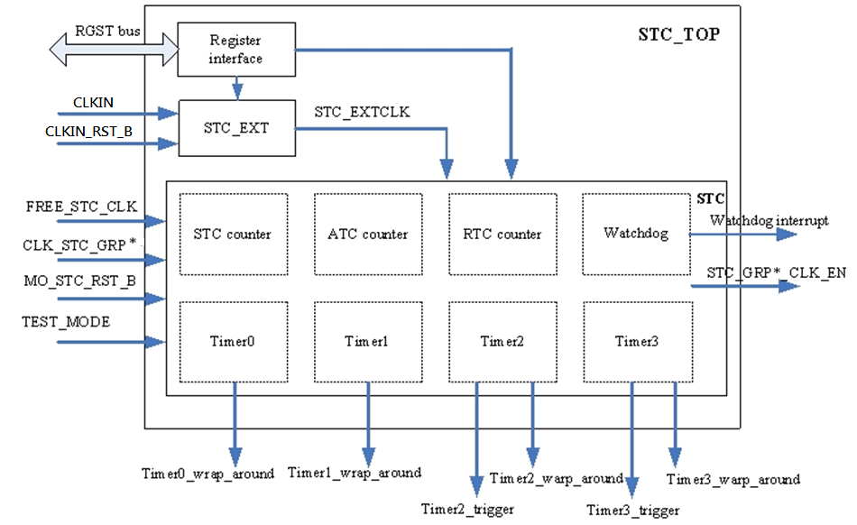
Figure 10-1 Timer Functional Blocks
- Timer0: A 1116-bit timer.
- Timer1: A 1116-bit timer.
- Timer2: A 16-bit timer.
- Timer3: A 16-bit timer.
- Watchdog Timer: A 20-bit timer
- RTC counter: A 24-bit real time counter.
- ATC counter: A 2434-bit attendance timer counter.
- STC counter: A 33-bit standard timer counter
- STC_EXT: Generate STC_EXTCLK block
- Register interface: The interface of timer module communication with CPU.
...
Figure 10-2 shows the timer0 and timer1 data trigger flow block diagram.
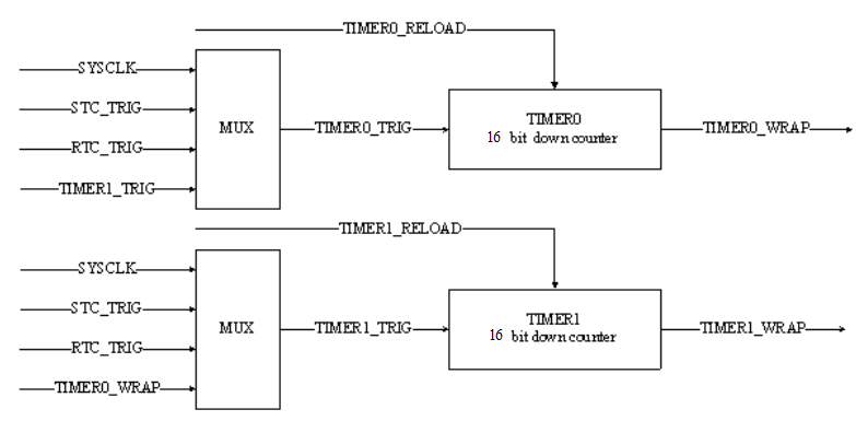
Figure 10-2 Timer0/1 Data Trigger Flow
...
10.3.1 Time Base Operation
The 2 timers provide an 1116-bit down-counter. When enable, it will down-count with a reference timing signal selecting from appropriate inputs (Refer to RGST table Group 12.8 timer0_ctl and Group 12.10 timer1_ctl registers). The interrupt will be asserted a pulse (a system clock cycle) if timer0/1 counter TIMER0_CNT/ TIMER1_CNT (Refer to RGST table Group 12.9 timer0_cnt and Group 12.11 timer1_cnt registers) reaches 0 and trigger asserts.
...
When timer0/1 counter reaches 0, the reload value (Refer to RGST table Group 12.30 timer0_reload and Group 12.31 timer1_reload registers) will be loaded into timer0/1 counter with repeat mode. RGST table Group 12.8 timer0_ctl bit13 set 1 as repeat mode. RGST table Group 12.10 timer1_ctl bit13 set 1 as repeat mode.
The 2 timers also provide one shot operation when RGST table Group 12.8 timer0_ctl and Group 12.10 timer1_ctl bit13 set 0. In this mode, timer will stop and clear GO flag (bit-11) automatically when the timer0/1 counter reaches 0.
When timer 0/1 reload value (TIME0_RELOAD/TIME1_RELOAD in waveform) changes, which the timer 0/1 counter will not respond to the change immediately until timer0/1 counter reaches 0. Please refer to the figure 10-3.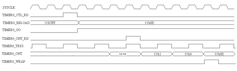
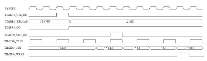
Figure 10-3 Timer0/Timer1 Counter Repeat Mode Timing Diagram
...
The RGST table Group 12.8 timer0_ctl bit[15:14] can select timer0 trigger source. Set 0 is selected SYSCLK, set 1 is selected STC_TRIG, set 2 is selected RTC_TRIG and set 3 is selected TIMER1_WRAP. The cooresponding function control bit of timer1 is Group 12.10 timer1_ctl bit[15:14].
10.3.4
...
32-bit counter mode
The Timer0/1 can combine to 2232-bit counter. For example, set timer0 trigger source as SYSCLK and set timer1 trigger source as TIMER0_WRAP, then the timer0+timer1 become a 2232-bit counter. When tm0timer0_count reaches 0, it will trigger TIMER0_WRAP to let tm1timer1_count down count and timer0_reload will be reloaded into tm0timer0_count at the same time. Repeat this action, finally the timer0+timer1 will operate like a 2232-bit counter.
10.3.5 Pause mode
...
STC (Standard Timer Counter) is has a 14-bit pre-scaler and a 33-bit counter. As Figure 1710-5, STC pre-scaler will divide the SYSCLK or STC_EXTCLK then generate STC_TRIG signal.
In the applications, STC_TRIG usually is a 90 kHz signal. STC Counter will increase after trigger by STC_TRIG. This is the outline of the STC counter working mode. The paragraph follows will explain the pre-scaler and counter details.
- STC pre-scaler: When pre-scaler reload value changed (STC_PRES_RELOAD in the figure), pre-scaler counter will clean to 0 right now. The divider relation is STC_TRIG = SYSCLK / (stc_prescaler+1).
- STC counter: It is a 3233-bit width counter. It will increase by STC_TRIG trigger. When the counter count to the max value, if STC_TRIG come again, which action will cause overflow. The STC counter support dynamic read/write, but the value maybe not precise. So for read operation add latch-read mode. The STC counter value is latched when CPU write any value to Group 12.26 stcl_2 bit32.
...
RTC (Real Time Counter) is a 1424-bit width counter. RTC Pre-scaler trigger source is STC_TRIG. It is different trigger source with STC Pre-scaler/Counter. And RTC counter doesn't support latch-read mode, other feature is the same with STC Pre-scaler/Counter
...
Address | Group No. | Register Name | Description |
|---|---|---|---|
0x9C000600 | G12.0 | stc_15_0 | STC Counter Register |
0x9C000604 | G12.1 | stc_31_16 | STC Counter Register |
0x9C000608 | G12.2 | stc_32 | STC Counter Register |
0x9C00060C | G12.3 | stc_divisor | STC pre-scaling Register |
0x9C000610 | G12.4 | rtc_15_0 | RTC Counter Register |
0x9C000614 | G12.5 | rtc_23_16 | RTC Counter Register |
0x9C000618 | G12.6 | rtc_divisor | RTC Divider Register |
0x9C00061C | G12.7 | stc_config | External reference clock divisor |
0x9C000620 | G12.8 | timer0_ctl | Timer0 Control Register |
0x9C000624 | G12.9 | timer0_cnt | Timer0 Counter Register |
0x9C000628 | G12.10 | timer1_ctl | Timer1 Control Register |
0x9C00062C | G12.11 | timer1_cnt | Timer1 Counter Register |
0x9C000630 | G12.12 | timerw_ctl | Watchdog Timer Control register |
0x9C000634 | G12.13 | timerw_cnt | Watchdog Timer Counter register |
0x9C000638 | G12.14 | stc 47 32 | STC Counter Register |
0x9C00063C | G12.15 | stc 63 48 | STC Counter Register |
0x9C000640 | G12.16 | timer2_ctl | Timer2 Control Register |
0x9C000644 | G12.17 | timer2_pres_value | Timer2 16-bit pre-scaling value |
0x9C000648 | G12.18 | timer2 reload | Timer2 16-bit reload value |
0x9C00064C | G12.19 | timer2_cnt | Timer2 16-bit counter value |
0x9C000650 | G12.20 | timer3_ctl | Timer3 Control Register |
0x9C000654 | G12.21 | timer3_pres_value | Timer3 16-bit pre-scaling value |
0x9C000658 | G12.22 | timer3_reload | Timer3 16-bit reload value |
0x9C00065C | G12.23 | timer3_cnt | Timer3 16-bit counter value |
0x9C000660 | G12.24 | stcl_0 | Latched value (bit 15:0) of STC counter |
0x9C000664 | G12.25 | stcl_1 | Latched value (bit 31:16) of STC counter |
0x9C000668 | G12.26 | stcl_2 | Latched value (bit 32) of STC counter |
0x9C00066C | G12.27 | atc_0 | 34 bit ATC counter [15:0] |
0x9C000670 | G12.28 | atc_1 | 34 bit ATC counter [31:16] |
0x9C000674 | G12.29 | atc_2 | 34 bit ATC counter [33:32] |
0x9C000678 | G12.30 | timer0 reload | Timer0 16-bit reload value |
0x9C00067C | G12.31 | Timer1 reload | Timer1 16-bit reload value |
...
12.9 Timer0 Counter register (timer0 cnt)
Address: 0x9C000624
Reset: 0x0000
| Field Name | Bit | Access | Description |
| timer0_cnt | 15: |
0 |
10:0
RW
Timer0 Count
Timer0 11-bit counter value. When timer0 is activated, this counter will count down to zero when triggered by specified clock source. When tm0 count reaches 0 and trigger asserts, timer0 interrupt will be assertedRW | Timer0 16-bit counter value Timer0 16-bit counter value. When timer0 is activated, it will count down to zero when triggered by specified clock source. |
12.10 Timer1 Control Register (timer1 ctl)
Address: 0x9C000628
Reset: 0x0000
...
12.11 Timer1 Counter register (timer1 cnt)
Address: 0x9C00062C
Reset: 0x0000
| Field Name | Bit | Access | Description | ||||
| Reservedtimer1_cnt | 15 | :11RO | Reserved | tm1_count | 10:0 | RW | Timer1 Count 16-bit counter value Timer1 1116-bit counter value. When timer1 is activated, this counterit will will count down to zero when triggered by specified clock sourceclock source. |
12.12 Watchdog Timer Control register (timerw ctl)
Address: 0x9C000630
Reset: 0x0000
...
| Field Name | Bit | Access | Description |
| timerw_cnt | 15:0 | RW | Watchdog Timer Count Watchdog timer is a 20-bit down-counting based on CLKstc (90kHz typically). The down-counting value is 0xfffff after reset. This register is from bit 4 to bit 19 of the watchdog timer counter (bit 3 to bit 0 can't be read or written, and timerw cnt [3:0] will be cleared automatically when the register is written). When timerw cnt counts down to zero, a flag (level interrupt) will be set immediately and hen the interrupt will trigger system level reset, but not reset internal registers of STC. To Write this register when TIMERW LOCK is 0. |
...
| Field Name | Bit | Access | Description |
| stc_63_48 | 15:0 | RW | STC counter Bit 63-48 of the 65-bit STC counter . |
12.16 Timer2 Control Register (timer2 ctl)
Address: 0x9C000640
Reset: 0x0000
...